
Display panel and display device

A display panel and display area technology, which is applied in the direction of semiconductor devices, electrical components, circuits, etc., can solve problems such as lowering the yield rate of the display panel, defective black spots, and package failure

Active Publication Date: 2020-05-29
BOE TECH GRP CO LTD +1
View PDF8 Cites 4 Cited by
  • Summary
  • Abstract
  • Description
  • Claims
  • Application Information

AI Technical Summary

Problems solved by technology

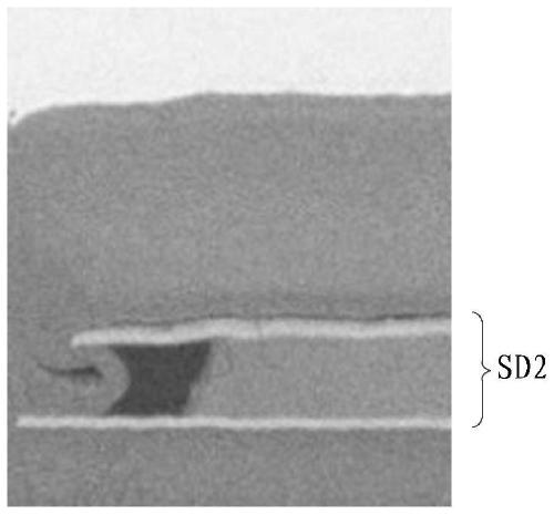
However, in the process of forming the pattern of the anode layer on the pattern of the uppermost source-drain electrode layer, the side edges of the uppermost layer of source-drain electrode layer are easily corroded by the wet etching solution. During Vapor Deposition (CVD), an abnormal state will be formed, resulting in package failure, and then causing water and oxygen from the outside to easily enter the display area along the boundary of the source-drain electrode layer, resulting in defective black spots, thereby reducing the yield of the display panel.

Method used


Image

  • Display panel and display device
  • Display panel and display device
  • Display panel and display device

Examples


Embodiment Construction

[0032] In order to make the purpose, technical solutions and advantages of the embodiments of the present invention more clear, the following will clearly and completely describe the technical solutions of the embodiments of the present invention in conjunction with the drawings of the embodiments of the present invention. Apparently, the described embodiments are some, not all, embodiments of the present invention. And in the case of no conflict, the embodiments in the present invention and the features in the embodiments can be combined with each other. Based on the described embodiments of the present invention, all other embodiments obtained by persons of ordinary skill in the art without creative efforts shall fall within the protection scope of the present invention.

[0033] Unless otherwise defined, the technical terms or scientific terms used in the present invention shall have the usual meanings understood by those skilled in the art to which the present invention be...


PUM


Abstract

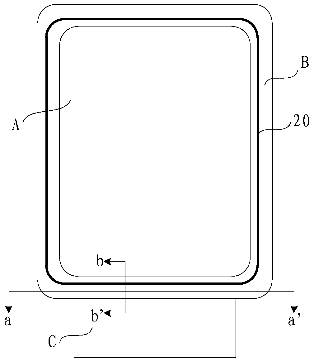
The invention provides a display panel and a display device. The display panel comprises a substrate, a blocking dam, a first source and drain electrode layer and a second source and drain electrode layer; the substrate comprises a display region, a non-display region surrounding the display region, and a binding region surrounding a part of the non-display region; the blocking dam is arranged around the non-display region; the first source and drain electrode layer and the second source and drain electrode layer are sequentially stacked on the substrate; the first source and drain electrode layer and the second source and drain electrode layer sequentially penetrate through the blocking dam; in an area, close to the binding area, of the non-display region, the first source and drain electrode layer comprises a first part and a second part which are arranged at an intervals; the second source and drain electrode layer is of a whole-layer structure; the second source and drain electrodelayer is electrically connected with the second part to form a low-potential wire; and the first part forms a high-potential wire. Poor performance caused by the corrosion of the side surfaces of thesource and drain electrode layers can be avoided, and the yield of the display panel is improved.

Description

technical field [0001] The present invention relates to the field of display technology, in particular to a display panel and a display device. Background technique [0002] In the field of display technology, compared with Liquid Crystal Display (LCD), Organic Light Emitting Diode (OLED) has the advantages of self-illumination, low energy consumption, low production cost, wide viewing angle, high contrast ratio, With the advantages of fast response, more realistic color display, and easier thinning and flexibility, it is widely used in display devices such as vehicles, mobile phones, tablets, and computers. [0003] The mainstream driving method of OLED is current drive, and the working current is transmitted from the lower frame (frame area) of the display panel through the source / drain (SD), because SD itself has a certain resistance, and there is a resistance drop in signal transmission ( IRDrop) phenomenon, eventually leading to uneven brightness of the display panel, ...

Claims


Application Information

Patent Timeline
IPC IPC(8): H01L27/12H01L27/32
CPCH01L27/124H10K59/131
Inventor 张祎杨赵广洲张震
Owner BOE TECH GRP CO LTD
Learn More