Miniaturized ultra-wideband microstrip antenna

A technology of microstrip antenna and ultra-wideband, which is applied in the direction of antenna, resonant antenna, antenna grounding device, etc., to achieve the effect of small size and reduced size

Active Publication Date: 2020-05-29
SOUTHWEST JIAOTONG UNIV
View PDF7 Cites 5 Cited by
  • Summary
  • Abstract
  • Description
  • Claims
  • Application Information

AI Technical Summary

Problems solved by technology

Although the current research and application of microstrip antennas are very mature, there are still many problems worthy of research in the analysis and research of the electromagnetic scattering characteristics of microstrip antennas.

Method used


Image

  • Miniaturized ultra-wideband microstrip antenna
  • Miniaturized ultra-wideband microstrip antenna
  • Miniaturized ultra-wideband microstrip antenna

Examples


Embodiment Construction

[0042]In order to make the purpose, technical solutions and advantages of the embodiments of the present invention clearer, the technical solutions in the embodiments of the present invention will be clearly and completely described below in conjunction with the drawings in the embodiments of the present invention. Obviously, the described embodiments It is a part of embodiments of the present invention, but not all embodiments. The components of the embodiments of the invention generally described and illustrated in the figures herein may be arranged and designed in a variety of different configurations. Accordingly, the following detailed description of the embodiments of the invention provided in the accompanying drawings is not intended to limit the scope of the claimed invention, but merely represents selected embodiments of the invention. Based on the embodiments of the present invention, all other embodiments obtained by persons of ordinary skill in the art without crea...


PUM


Abstract

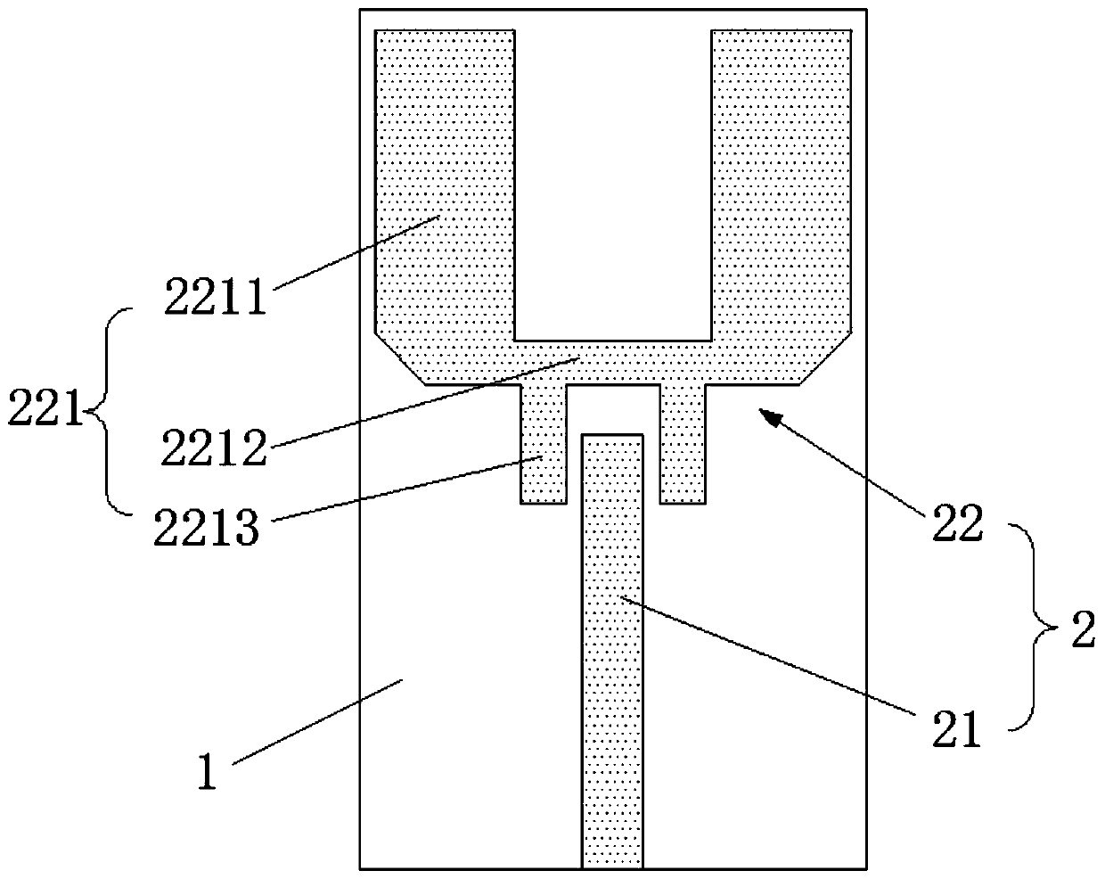
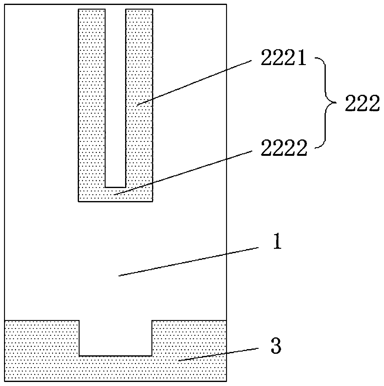
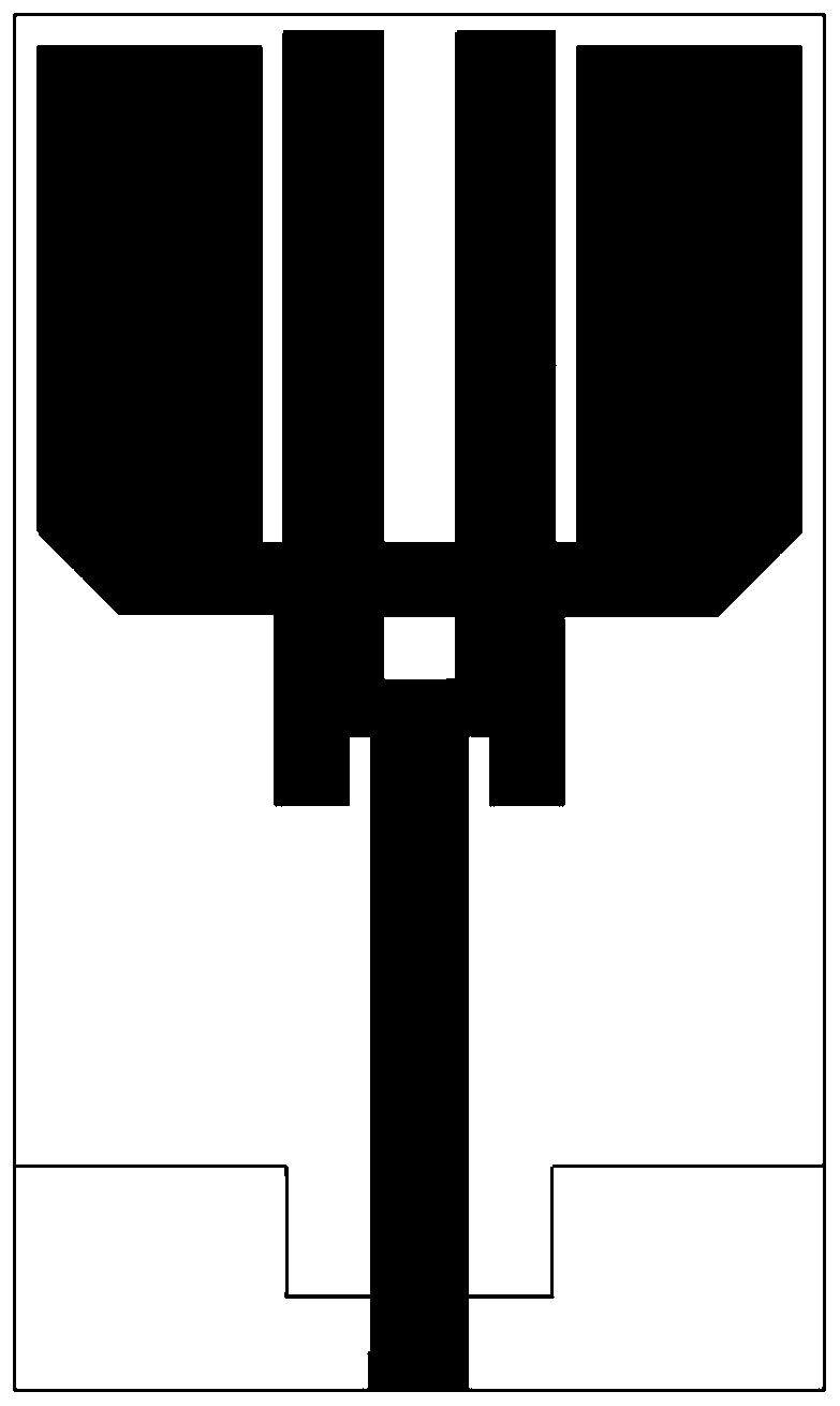
The invention relates to the technical field of antennas, and particularly relates to a miniaturized ultra-wideband microstrip antenna. The antenna comprises a substrate, and a radiation patch and a grounding part are arranged on the substrate; the radiation patch comprises a monopole and a coupling structure; the coupling structure comprises a first part and a second part; the first part and thesecond part are arranged on two sides of the substrate; the first part comprises a second sub-patch, two parallel first sub-patches and two parallel third sub-patches, and the two first sub-patches and the two parallel third sub-patches are arranged on the two sides of the second sub-patch respectively; and the second part is a U-shaped structure. A size of the ultra-wideband microstrip antenna isonly 20mm*34mm, the ultra-wideband microstrip antenna has the small size, and the ultra-wideband microstrip antenna also has advantages of an ultra-wideband, a high gain and good omnidirectivity under the condition that the size is reduced. According to the antenna, an effective working frequency band is 3.05-11.08GHz, a total bandwidth is 8GHz, an average gain is higher than 5dBi, a peak value is 8.2dBi, and an omnidirectional radiation characteristic is achieved at 3.1-6GHz.

Description

technical field [0001] The invention relates to the technical field of antennas, in particular to a miniaturized ultra-wideband microstrip antenna. Background technique [0002] The microstrip antenna is on a thin dielectric substrate, one side is attached with a thin metal layer as a ground plane, and the other side is made of a metal patch of a certain shape by photolithography and etching, and the patch is fed by a microstrip line or a coaxial probe composed of antennas. Microstrip antennas include microstrip vibrator antennas in the form of slender strips, and also in the form of area units. The area unit can be equivalent to a resonant cavity, and good radiation characteristics can be obtained near its resonant frequency, that is, in the working frequency band. Although the research and application of microstrip antennas are very mature, there are still many problems worth studying in the analysis and research of the electromagnetic scattering characteristics of micros...

Claims


Application Information

Patent Timeline
Patent Type & Authority Applications(China)
IPC IPC(8): H01Q1/38H01Q1/48H01Q1/50H01Q5/25H01Q9/30H01Q13/08
CPCH01Q1/38H01Q1/48H01Q1/50H01Q5/25H01Q9/30H01Q13/08
Inventor 马征肖波吴彦良邓文强张雯睿陈要廷
Owner SOUTHWEST JIAOTONG UNIV
Why Eureka
Try Eureka