
Laser radar system and laser detection method thereof

A laser radar and laser light source technology, applied in the field of laser detection, can solve the problems of increasing the number of lasers, reducing costs, disadvantages, etc., and achieve the effect of reducing the occupied volume of equipment, ensuring the integrity, and reducing the occupied space volume

Inactive Publication Date: 2020-06-02
NINGBO SUNNY AUTOMOTIVE OPTECH
View PDF2 Cites 1 Cited by
  • Summary
  • Abstract
  • Description
  • Claims
  • Application Information

AI Technical Summary

Problems solved by technology

Multiple laser irradiation sources are also a feasible attempt, but this will undoubtedly increase the number of lasers and consume exponentially increased energy, which is not conducive to reducing cost and lidar volume

Method used


Image

  • Laser radar system and laser detection method thereof
  • Laser radar system and laser detection method thereof
  • Laser radar system and laser detection method thereof

Examples


Embodiment Construction

[0071] The following description serves to disclose the present invention to enable those skilled in the art to carry out the present invention. The preferred embodiments described below are only examples, and those skilled in the art can devise other obvious variations. The basic principles of the present invention defined in the following description can be applied to other embodiments, variations, improvements, equivalents and other technical solutions without departing from the spirit and scope of the present invention.

[0072] Those skilled in the art should understand that in the disclosure of the present invention, the terms "vertical", "transverse", "upper", "lower", "front", "rear", "left", "right", " The orientation or positional relationship indicated by "vertical", "horizontal", "top", "bottom", "inner", "outer", etc. is based on the orientation or positional relationship shown in the drawings, which are only for the convenience of describing the present invention...


PUM


Abstract

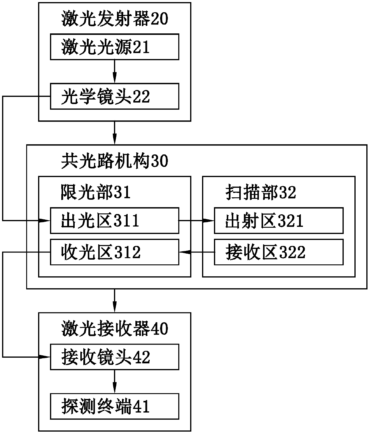
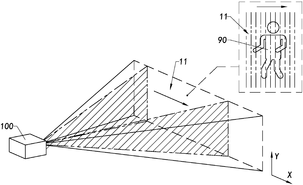
The invention provides a laser radar system comprising a laser transmitter, a common optical path mechanism, and a laser receiver. The laser generator provides a light ray for the common optical pathmechanism. The laser receiver receives the reflected light rays recovered by the common optical path mechanism. The laser transmitter and the laser receiver are arranged at one end of the common optical path mechanism, and the light paths of the light rays and the reflected light rays in the common optical path mechanism coincide. In addition, the invention provides a laser detection method, detection work is carried out in a common-optical-path scanning mode, the occupied space of equipment is reduced, the space utilization rate is increased, and the scanning resolution and precision are guaranteed.

Description

technical field [0001] The invention relates to the field of laser detection, in particular to a laser radar system using a common optical path and a method thereof. Background technique [0002] Lidar is a technology that uses laser for radar detection. It uses laser as a light source to emit laser pulses to the target, and obtains information such as distance and azimuth of the target by receiving the laser signal reflected by the target (including physical information such as amplitude and phase). Realize three-dimensional detection of the surrounding environment. [0003] Currently more mature lidar systems include mechanical lidar systems and micro-electro-mechanical systems (Micro-Electro-Mechanical System, MEMS) lidar systems. [0004] The former uses the motor to drive the mechanical shaft to realize the rotation of the entire transceiver system, and realizes the scanning of the surrounding environment through the rotation of the transmitting unit. During use, the ...

Claims


Application Information

Patent Timeline
Patent Type & Authority Applications(China)
IPC IPC(8): G01S17/02
CPCG01S17/02
Inventor 徐超沈阳杨佳
Owner NINGBO SUNNY AUTOMOTIVE OPTECH
Learn More