
Ultraviolet sterilization and disinfection lamp and control method thereof

A technology of sterilization and ultraviolet rays, which is applied in disinfection, irradiation, deodorization, etc., can solve problems such as blindness, redness and swelling of eyes, and burnt skin, and achieve the effects of enhancing disinfection, increasing sterilization, and reducing noise

Pending Publication Date: 2020-06-05
ZHEJIANG FUERJ ELECTRIC SCI & TECH
View PDF0 Cites 7 Cited by
  • Summary
  • Abstract
  • Description
  • Claims
  • Application Information

AI Technical Summary

Problems solved by technology

Among the ultraviolet rays, the UVC ultraviolet rays are the ones that really have a bactericidal effect, because the C-band ultraviolet rays are easily absorbed by the DNA of microorganisms. The UVC band, with a wavelength of 100-275nm, has the weakest penetrating ability and cannot penetrate most transparent glass and Plastic, the short-wave ultraviolet rays contained in sunlight are almost completely absorbed by the ozone layer, but short-wave ultraviolet rays are very harmful to the human body. Short-term exposure can burn the skin, long-term or high-intensity exposure can also cause skin cancer, and ultraviolet rays are very harmful to human eyes. Harmful, short-term exposure to large doses can cause redness, swelling, tearing, and inability to open eyes; long-term exposure to ultraviolet radiation can cause cataracts and even blindness

Method used


Image

  • Ultraviolet sterilization and disinfection lamp and control method thereof
  • Ultraviolet sterilization and disinfection lamp and control method thereof
  • Ultraviolet sterilization and disinfection lamp and control method thereof

Examples


Embodiment 1

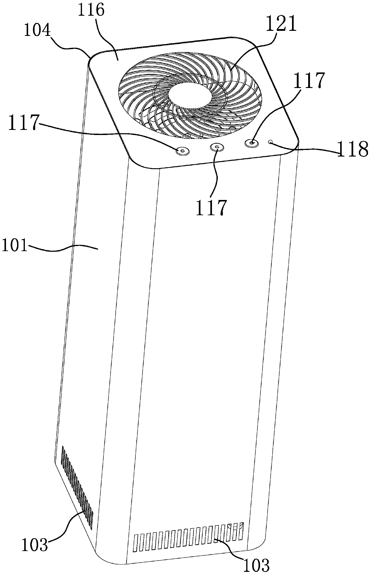
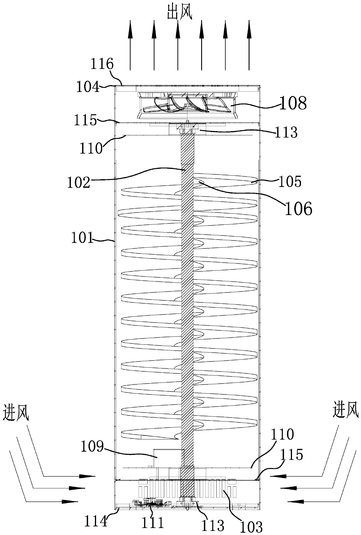
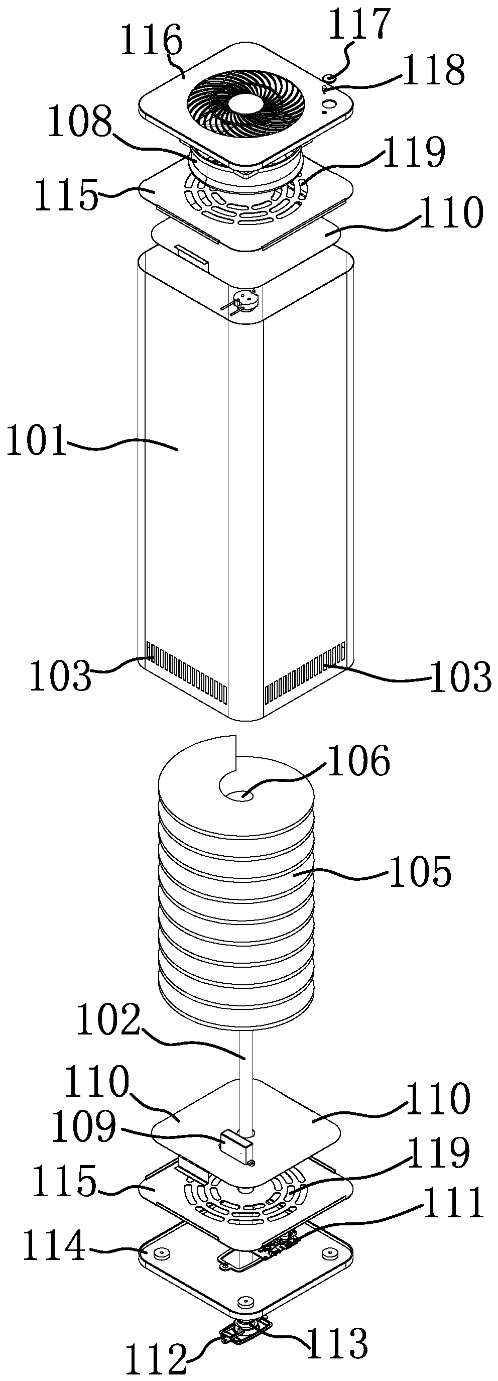
[0044] Such as Figures 1 to 4As shown, the ultraviolet sterilizing and disinfection lamp in this embodiment is a vertical structure, and the lamp housing 101 is arranged vertically. The lamp housing 101 is provided with an air outlet 104 at the top and an air inlet 103 at the bottom. There is an ultraviolet lamp tube 102, and the lamp housing 101 itself or its inner side here is made of a material that prevents the ultraviolet rays emitted by the ultraviolet lamp tube 102 through the lamp housing 101 to radiate to the outside world, so that people can Still can be close to this disinfection lamp and can not be damaged by the ultraviolet ray that ultraviolet lamp tube 102 sends, also be provided with the following wind-blocking structure, draft structure, and control part in addition, here ultraviolet lamp tube 102, draft structure and The control components are electrically connected.

[0045] It should be noted that, if figure 1 Shown is the mechanical version of the prese...

Embodiment 2

[0058] This embodiment is basically the same as Embodiment 1, except that the wind-blocking structure here is made of a material that reflects and / or refracts the ultraviolet rays emitted by the ultraviolet lamp 102, and the outer surface of the wind-blocking structure is The smooth structure is beneficial for the wind-blocking structure to better reflect or refract the ultraviolet rays when it is irradiated by the ultraviolet rays emitted by the ultraviolet lamp tube 102, so that the advancing wind can receive ultraviolet rays from more angles to enhance its sterilization Effect.

[0059] Preferably, the outer surface of the wind blocking structure is a mirror structure, so as to improve its reflection function on ultraviolet rays, which is beneficial to strengthen the sterilization and disinfection effect of the reflected ultraviolet rays on the traveling wind.

[0060] It should be noted that there are many materials that can reflect or refract ultraviolet rays, generally b...

Embodiment 3

[0063] This embodiment is basically the same as Embodiment 1 and 2, the difference is: as Figures 5 to 7 As shown, the wind blocking structure here is another structure, specifically, it includes a number of plate-shaped partitions 107 that make the wind flowing into the lamp housing 101 advance toward the air outlet 104 in a bent shape, and the adjacent plate-shaped partitions The partitions 107 are arranged in a staggered manner along the direction of the wind, and the wind flowing into the lamp housing 101 flows out through the gap between every two adjacent plate-shaped partitions 107 .

[0064] Such as Image 6 As shown, a lamp tube hole 106 for the ultraviolet lamp tube 102 to pass through is opened on the side of the plate-shaped spacer 107 close to the middle of the lamp housing 101 .

[0065] Such as Figure 5 with 6 As shown, the sum of the areas of each adjacent two plate-shaped partitions 107 is at least substantially the same as the size of the cross-section i...


PUM


Abstract

The invention provides an ultraviolet sterilization and disinfection lamp and a control method thereof, and belongs to environment-friendly equipment. According to the ultraviolet sterilization and disinfection lamp and the control method, the problem that an ultraviolet sterilization and disinfection lamp adopting the design in the prior art is capable of sterilizing and disinfecting air but generates great injury to people irradiated by the ultraviolet sterilization and disinfection lamp at the same time is solved. The ultraviolet sterilization and disinfection lamp comprises a lamp shell and an ultraviolet lamp tube arranged in the lamp shell. The ultraviolet sterilization and disinfection lamp is characterized in that the lamp shell and the inner side of the lamp shell are prepared from materials capable of blocking ultraviolet light emitted by the ultraviolet lamp tube and radiating the ultraviolet light outwards through the lamp shell, and an air inlet, an air outlet and the likeare formed in the lamp shell. The ultraviolet sterilization and disinfection lamp has the advantages that the ultraviolet sterilization and disinfection lamp adopts a closed structure to cover the light, an exhausting device is utilized for drawing surrounding air into a closed shell container, and air is subjected to sectional sterilization and disinfection by virtue of a partition board and isthen exhausted out, so that sterilization of air can be realized, and a user beside the ultraviolet sterilization and disinfection lamp is not influenced by radiation.

Description

technical field [0001] The invention belongs to environmental protection equipment, in particular to an ultraviolet sterilizing lamp. Background technique [0002] Ultraviolet sterilization is to destroy and change the DNA (deoxyribonucleic acid) structure of microorganisms through ultraviolet irradiation, so that the bacteria die immediately or cannot reproduce offspring, so as to achieve the purpose of sterilization, and ultraviolet sterilization is a purely physical disinfection method without secondary pollution. Among the ultraviolet rays, the UVC ultraviolet rays are the ones that really have a bactericidal effect, because the C-band ultraviolet rays are easily absorbed by the DNA of microorganisms. The UVC band, with a wavelength of 100-275nm, has the weakest penetrating ability and cannot penetrate most transparent glass and Plastic, the short-wave ultraviolet rays contained in sunlight are almost completely absorbed by the ozone layer, but short-wave ultraviolet ray...

Claims


Application Information

Patent Timeline
Patent Type & Authority Applications(China)
IPC IPC(8): A61L9/20A61L9/22
CPCA61L9/20A61L9/22
Inventor 罗建富
Owner ZHEJIANG FUERJ ELECTRIC SCI & TECH
Learn More