Electromagnetic driving vacuum die-casting machine

A technology of vacuum die-casting and electromagnetic drive, which is applied in the field of precision parts forming, and can solve problems such as the start-up time and long distance of the injection rod, and achieve the effect of shortening start-up time, reducing maintenance time and improving overall efficiency

Inactive Publication Date: 2020-06-05
YANSHAN UNIV
View PDF7 Cites 2 Cited by
  • Summary
  • Abstract
  • Description
  • Claims
  • Application Information

AI Technical Summary

Problems solved by technology

[0005] Aiming at the above problems urgently needed to be solved by the vacuum die-casting machine, the present invention provides an electromagnetic-driven vacuum die-casting machine, which is mainly based on electromagnetic power, which solves the problems of too long start-up time and distance of the traditional plunger, and can be used in a very short time Achieve the injection speed and injection force required for injection, so as to realize the compact structure and small volume of die casting equipment, and also improve the quality and efficiency of amorphous alloy preparation

Method used


Image

  • Electromagnetic driving vacuum die-casting machine
  • Electromagnetic driving vacuum die-casting machine
  • Electromagnetic driving vacuum die-casting machine

Examples


Embodiment Construction

[0030] In order to detail the technical content, structural features, achieved goals and effects of the present invention, the following will be described in detail in conjunction with the accompanying drawings.

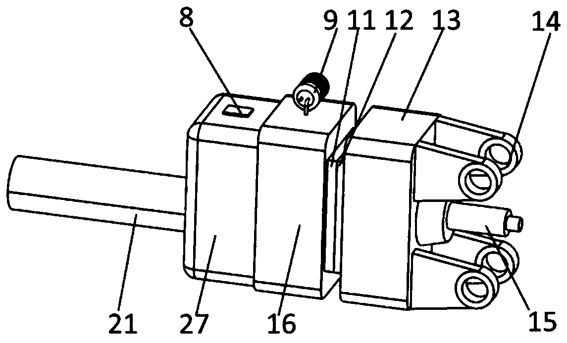
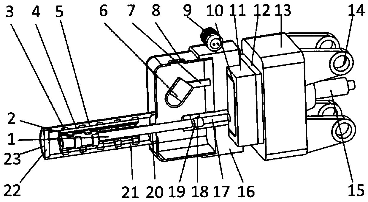
[0031] Solenoid-driven vacuum die-casting machines, such as figure 1 and figure 2 As shown, it includes a drive assembly, a fixed mold assembly, a movable mold assembly, an executive assembly, a sealing ring 10 and a rectangular shell 27 .

[0032] drive components such as figure 2As shown, it includes a stator assembly and a mover assembly. The stator assembly includes a stator ferromagnetic ring 3 , a stator winding 4 , a stator magnetic isolation ring 5 , a heat shield 20 , a cylindrical shell 21 and a rear cover 22 . The cylindrical shell 21 is welded by the same two semicircles, the back cover 22 is located at the first end inside the cylindrical shell 21, the heat shield 20 is located at the second end inside the cylindrical shell 21, and the stator ferroma...


PUM


Abstract

The invention provides an electromagnetic driving vacuum die-casting machine. The electromagnetic driving vacuum die-casting machine comprises a driving assembly, a fixed die assembly, a movable die assembly and an executing assembly; a rear cover and a heat insulation plate are respectively positioned at the two ends of a cylindrical shell; a stator ferromagnetic ring is positioned inside the cylindrical shell; a rotor sleeve is positioned inside the stator ferromagnetic ring; a stator winding is connected with an iron core of the stator ferromagnetic ring; stator magnetic isolation rings areuniformly distributed on the inner surface of the cylindrical shell; rotor fan-shaped salient poles are uniformly distributed on the rotor sleeve; a fixed die plate is connected with a fixed die; thefixed die is connected with a movable die; the movable die is connected with a movable die plate; a pressure chamber is positioned inside a rectangular shell, the fixed die plate and the fixed die; amolten metal pouring gate is positioned at the upper part of the second end of the pressure chamber; the first end of the pressure chamber is connected with an inflow hole of a transverse pouring channel; the first end of an injection rod is connected with the rotor sleeve; the second end of the injection rod is connected with an injection plunger; and the injection plunger is positioned at the second end of the pressure chamber. According to the electromagnetic driving vacuum die-casting machine, the starting time can be shortened through the electromagnetic driving, the speed required by injection can be reached in a very short time, the eddy current loss is small, and the electromagnetic driving vacuum die-casting machine has the characteristics of large average injection force.

Description

technical field [0001] The invention relates to the technical field of forming precision parts, in particular to an electromagnetically driven vacuum die-casting machine. Background technique [0002] At present, with the continuous deepening of research on amorphous alloys, numerous research results have been formed. As a new type of material with very high strength, hardness and corrosion resistance, amorphous alloy has obvious advantages in impact fracture performance. Its elastic modulus is very low but it can store a large amount of elastic energy, and its energy transfer performance is also very good. Amorphous alloys are widely used in the fields of precision mechanical instrument parts, electronic devices, aerospace devices and sports equipment. Although amorphous alloys show obvious advantages in all aspects, they have obvious glass transition, very high supercooled liquid stability and decrystallization thermal stability, and bulk amorphous alloys are extremely st...

Claims


Application Information

Patent Timeline
Patent Type & Authority Applications(China)
IPC IPC(8): B22D17/14B22D17/20B22D17/22
CPCB22D17/14B22D17/2015B22D17/2046B22D17/22
Inventor 金昕金渊哲詹望于学千
Owner YANSHAN UNIV
Why Eureka
Try Eureka