A plate cutting device for numerical control machining and its operating method

A cutting device and plate technology, which is applied to shearing devices, metal processing machinery parts, cutters for shearing machines, etc., can solve the problems of inaccurate cutting positions, low degree of automation, and poor working stability of the device, etc. To achieve the effect of precise cutting position, high degree of automation and flexibility

Active Publication Date: 2021-01-29
正德职业技术学院
View PDF6 Cites 0 Cited by
  • Summary
  • Abstract
  • Description
  • Claims
  • Application Information

AI Technical Summary

Problems solved by technology

[0004] The purpose of the present invention is to solve the low efficiency of the existing CNC machining plate cutting device for plate cutting; the automation of plate cutting is low, and the use of the cutting device is very time-consuming and laborious; The cutting position of the plate is inaccurate; and the incision made by the cutting device is not smooth enough, and the stability of the device is poor; and the range of the cutting blade on the cutting device that can be adjusted is too small; the cutting blade cannot be adjusted To flexibly adjust the position and direction of cutting the plate, the cutting device can cut the shape of the plate is too simple, and propose a plate cutting device for CNC machining and its operation method

Method used


Image

  • A plate cutting device for numerical control machining and its operating method
  • A plate cutting device for numerical control machining and its operating method
  • A plate cutting device for numerical control machining and its operating method

Examples


Embodiment Construction

[0030]The technical solutions of the present invention will be clearly and completely described below in conjunction with embodiments. Obviously, the described embodiments are only a part of the embodiments of the present invention, rather than all the embodiments. Based on the embodiments of the present invention, all other embodiments obtained by those of ordinary skill in the art without creative work shall fall within the protection scope of the present invention.

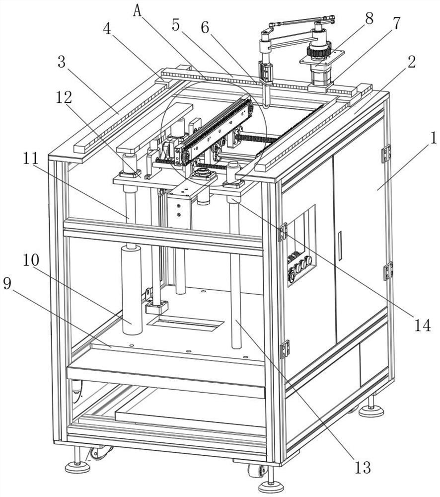
[0031]SeeFigure 1-4As shown, a plate cutting device for numerical control processing includes a vertical mounting frame 1, a vertical cutting table 8, a flat support plate 12, and two clamping frames 32. The top of the vertical mounting frame 1 is horizontally provided with a top The supporting plate 2, the top supporting plate 2 is provided with sliding rails one 3 on both sides, and the two sliding rails one 3 are covered with a hollow inverted U-shaped structure of the sleeve frame one 4, two sleeve frames one 4 Ther...


PUM


Abstract

The invention discloses a plate cutting device for numerical control machining and an operation method thereof, which comprises a vertically arranged vertical loading frame, a vertical cutting table, a flat support plate and two clamping frames, and the top of the vertical loading frame is horizontally arranged There is a top support plate, the two sides of the top support plate are provided with a sleeve slide rail 1, and the sleeve frame 1 of a hollow inverted U-shaped structure is sleeved on the two sleeve slide rails 1. The beneficial effects of the present invention are: the motor 4 drives the cutting piece to rotate to cut the plate, and cooperates with the sleeve frame 1 and the sleeve frame 2 to move on the sleeve slide rail 1 and the sleeve slide rail 2 respectively to adjust the cutting blade to cut the plate position, and cooperate with motor five to drive the chain through gear two, so as to drive the front and rear movement adjustment of the board. On the one hand, it greatly improves the cutting efficiency of the device for CNC machining boards and ensures that the device can cut the boards. The degree of automation of the work is higher, and the use of the work is more time-saving and labor-saving. On the other hand, it ensures that the device cuts the position of the plate more accurately.

Description

Technical field[0001]The invention relates to a cutting device, in particular to a plate cutting device for numerical control processing and an operation method thereof, and belongs to the technical field of cutting device application.Background technique[0002]In the CNC machining process, the cutting device is used more and more frequently. The cutting device is used to cut and shape different types of panels to facilitate the later use of the panels.[0003]The existing plate cutting device for numerical control processing still has many shortcomings in use. The existing plate cutting device for numerical control processing has low efficiency in cutting the plate and low degree of automation in the cutting and processing of the plate. The use of the cutting device is very time-consuming and laborious. The position of the cutting device for cutting plates of different thicknesses is not accurate, and the cut of the plate after the cutting device is not smooth enough, the stability of...

Claims


Application Information

Patent Timeline
IPC IPC(8): B23D19/00B23Q1/62B23Q1/30B23Q5/38B23Q5/26B23Q5/28B23Q5/10B23Q5/04B23D35/00B23D33/02
CPCB23D19/00B23D33/02B23D35/007B23Q1/30B23Q1/623B23Q5/045B23Q5/10B23Q5/26B23Q5/28B23Q5/385B23Q2240/002
Inventor 赵寿宽龚君
Owner 正德职业技术学院
Why Eureka
Try Eureka