Rock sample block stress field simulation device

一种岩石试样、模拟装置的技术,应用在使用施加稳定的张力/压力测试材料强度等方向,能够解决实施成本高、液压泵站系统复杂等问题,达到便于装配、经济实用、优化结构工艺性的效果

Active Publication Date: 2020-06-05
CHINA RAILWAY SHANHE ENG EQUIP CO LTD
View PDF7 Cites 7 Cited by
  • Summary
  • Abstract
  • Description
  • Claims
  • Application Information

AI Technical Summary

Problems solved by technology

However, due to the large size of the rock sample block required for the TBM wire cutting test (for example, in order to avoid the boundary effect caused by the small size of the rock sample block, the literature "Disc cutting tests inColorado Red Granite: Implications for TBM performance prediction" uses 1.1 × 0.8 × 0.6m granite sample), if a given ground stress level is simulated, the required hydraulic cylinder rated working pressure or hydraulic cylinder size specification is higher, correspondingly the configured hydraulic pump station system is more complex (including high-pressure pump, booster cylinder, etc.), and put forward extremely high requirements on the rigidity of the simulated loading device, system sealing performance and reliability, and the implementation cost is relatively high

Method used


Image

  • Rock sample block stress field simulation device
  • Rock sample block stress field simulation device
  • Rock sample block stress field simulation device

Examples


Embodiment 1

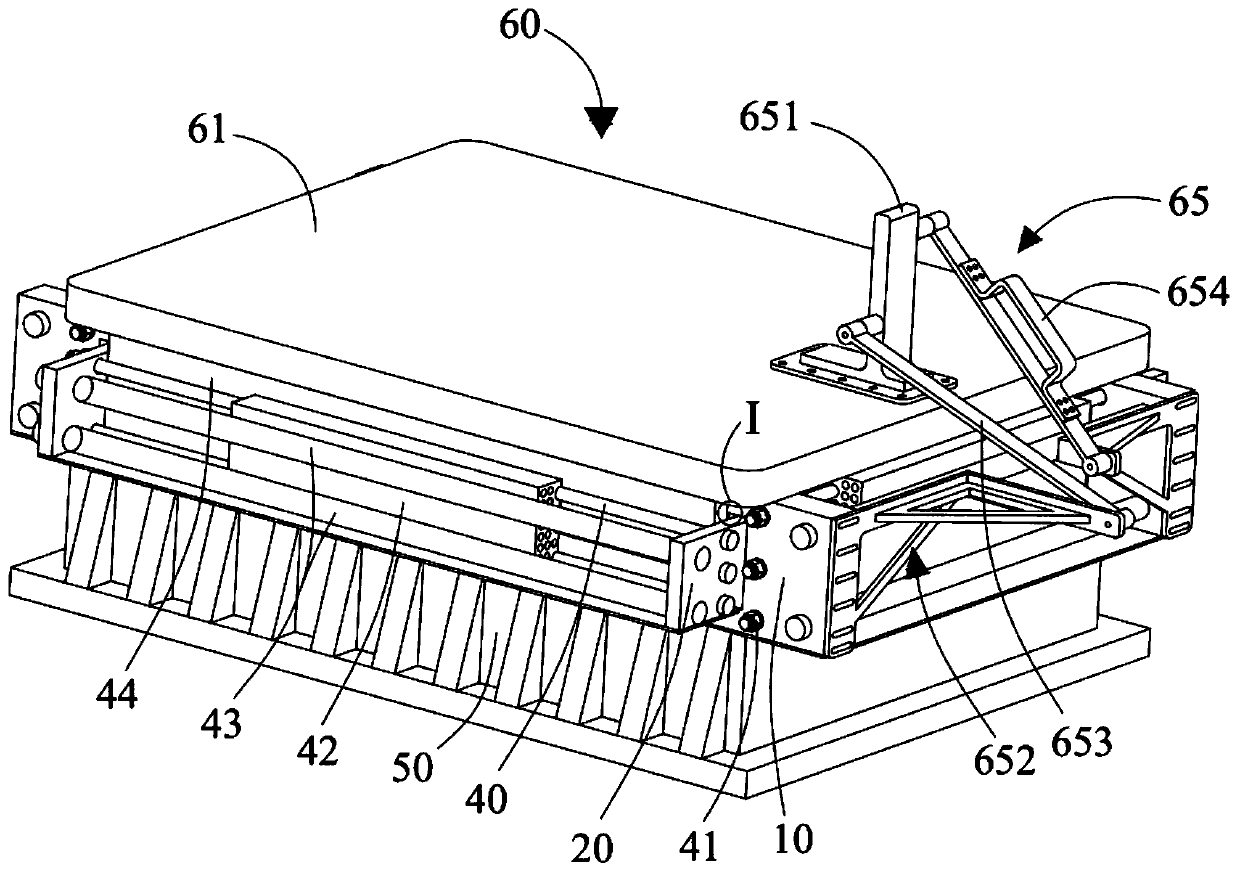
[0049] figure 1 It is a schematic diagram of the structure of the rock sample block stress field simulation device in Implementation 1. Such as figure 1 As shown, the rock sample block stress field simulation device includes a base 50 , a stress assembly and an upper cover assembly 60 . The stress assembly is arranged on the base 50, and is used to apply a stress field to the rock sample block 80 on the base 50, and the upper cover assembly 60 covers the rock sample block 80, and is used to apply a stress field to the rock sample block 80 on the base 50. Apply a temperature field.

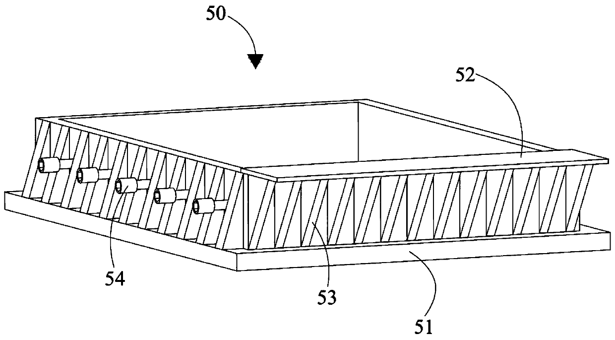
[0050] figure 2 is a structural schematic diagram of the base 50, such as figure 2 As shown, the base 50 includes a bottom plate 51 , a support plate 52 and a reinforcing rib 53 . The bottom plate 51 is generally plate-shaped and placed horizontally on the support. The support plate 52 has a plate shape and extends along a horizontal plane. The reinforcing rib 53 is connected between the b...

Embodiment 2

[0107] Figure 14 It is a structural schematic diagram of the stress field simulator of the rock sample block 80 in Implementation 2 (the base 50 is not shown). The difference between embodiment 2 and embodiment 1 is that the connection member 65 disclosed in embodiment 1 is not provided in embodiment 2, but embodiment 2 also includes a hob groove 73 and a hob mechanism 70 . In Embodiment 2, the upper cover assembly 60 further includes a hob groove 73 passing through the cover body 61 , the heating plate 62 and the heat conducting plate 63 . The hob mechanism 70 includes a moving frame 71 , a knife seat 74 and a hob 75 .

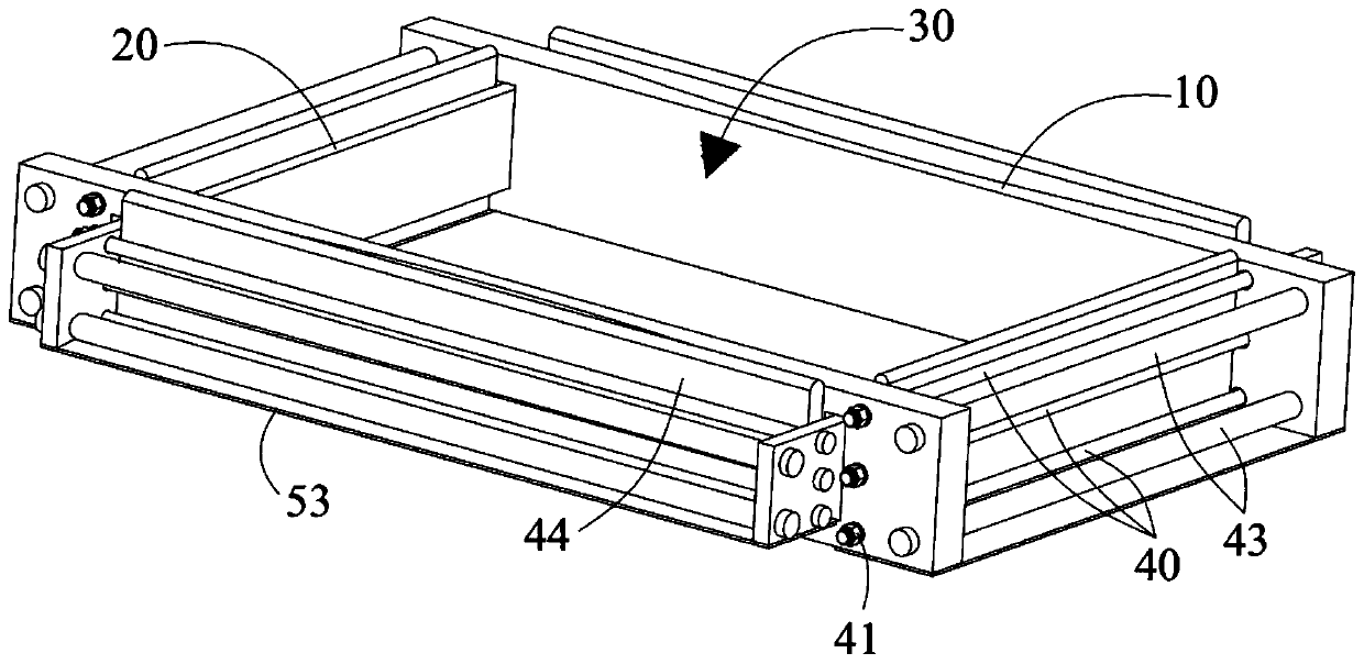
[0108] Figure 15 is a structural schematic diagram of the stress assembly and the mobile frame 71. Such as Figure 15 As shown, the moving frame 71 is connected to the first side plate 10 or the second side plate 20 , and the upper cover assembly 60 covers the stone bin 30 and is movably connected to the moving frame 71 . The mobile frame 71 is provide...


PUM


Abstract

A rock sample block stress field simulation device comprises a stress assembly, and the stress assembly comprises a pair of first side plates, wherein the first side plates are oppositely arranged, and mounting through holes are formed in the ends of the first side plates; a pair of second side plates which are oppositely arranged, wherein the end parts of the second side plates penetrate throughthe mounting through holes; a locking screw rod and a nut, wherein the two ends of the locking screw rod are connected between the pair of first side plates and / or between the pair of second side plates, and the nut is connected to the locking screw rod through threads; and a heating block which is in contact with the locking screw rod. According to the invention, the heating block is used for heating the locking screw rod to enable the locking screw rod to extend, and then the nut enables the first side plate and / or the second side plate to relatively move to apply a stress field to the rocksample block located in the stone bin; the device is simple in structure, economical, practical, convenient to install and convenient to operate.

Description

technical field [0001] The invention relates to the field of rock-soil tunnel equipment, in particular to a rock sample block stress field simulation device. Background technique [0002] The statements in this section merely provide background technical information related to the disclosure of the present invention, and do not necessarily constitute prior art. [0003] The rock mass existing in the formation, especially the natural rock mass in the deep rock stratum, on the one hand, due to the influence of factors such as gravity, plate movement and crustal contraction, is subjected to the effect of the in-situ stress (commonly known as confining pressure), and is in the in-situ stress field. On the other hand, due to the influence of geothermal sources, cutting heat, etc., it bears the temperature load and is in the temperature field. A series of documents such as "Change of Mechanical Properties of Coal Measures Rocks Under Deep In-situ Stress Field" and "Research on Nu...

Claims


Application Information

Patent Timeline
Patent Type & Authority Applications(China)
IPC IPC(8): G01N3/12
CPCG01N3/12Y02E10/10
Inventor 张魁刘海成刘艳玲彭赐彩郭龙何仕海
Owner CHINA RAILWAY SHANHE ENG EQUIP CO LTD
Why Eureka
Try Eureka