
Double-frequency three-order band-pass filter based on microstrip ridge gap waveguide

A gap waveguide and first-order band-pass technology, which is applied in the field of dual-frequency third-order band-pass filters, can solve the problems of fewer filters, large communication system volume, and no dual-frequency filters, etc., and achieves compact size and easy coupling strength , easy to independently control effects

Active Publication Date: 2020-06-05
XIDIAN UNIV
View PDF7 Cites 10 Cited by
  • Summary
  • Abstract
  • Description
  • Claims
  • Application Information

AI Technical Summary

Problems solved by technology

However, since microstrip gap waveguide technology has just been proposed as a new type of transmission line in recent years, there are few filter designs based on microstrip gap waveguide technology. At present, only single-frequency microstrip gap waveguide filters have been reported. With the trend of multi-protocol and multi-band development, the use of these single-frequency microstrip gap waveguide filters will lead to a larger overall volume of the communication system
[0003] In summary, the existing problems in the prior art are: the existing microstrip gap waveguide filters are all single-frequency filters, which do not meet the needs of multi-band work in communication systems
At present, no dual-band filter based on microstrip ridge-gap waveguide has been reported based on microstrip ridge-gap waveguide filter design.

Method used


Image

  • Double-frequency three-order band-pass filter based on microstrip ridge gap waveguide
  • Double-frequency three-order band-pass filter based on microstrip ridge gap waveguide
  • Double-frequency three-order band-pass filter based on microstrip ridge gap waveguide

Examples


Embodiment Construction

[0028] In order to make the object, technical solution and advantages of the present invention more clear, the present invention will be further described in detail below in conjunction with the examples. It should be understood that the specific embodiments described here are only used to explain the present invention, not to limit the present invention.

[0029] Aiming at the problems existing in the prior art, the present invention provides a dual-frequency third-order bandpass filter based on a microstrip ridge-gap waveguide. The present invention will be described in detail below in conjunction with the accompanying drawings.

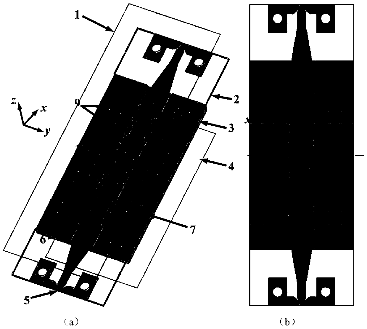
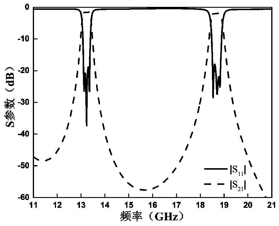
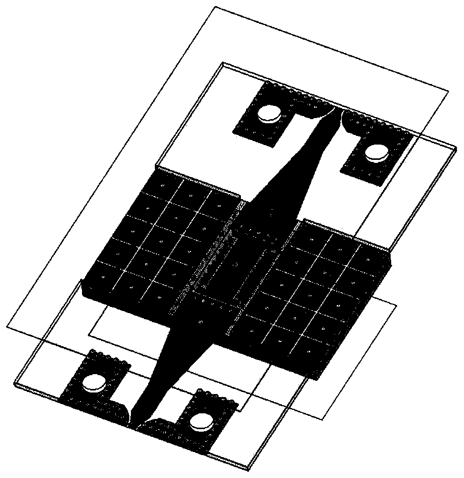
[0030] Such as figure 1 As shown, the dual-frequency third-order bandpass filter based on the microstrip ridge-gap waveguide provided by the embodiment of the present invention includes: two layers of dielectric boards: an upper dielectric board 2 and a lower dielectric board 3, and the upper surface of the dielectric board 3 is loaded with The u...


PUM


Abstract

The invention belongs to the technical field of microwave devices, and discloses a double-frequency three-order band-pass filter based on microstrip ridge gap waveguides. A metal floor is arranged onthe upper surface of an upper dielectric plate, metalized via holes are embedded in the two sides and the middle of the dielectric plate respectively, and a grounded coplanar waveguide-microstrip gapwaveguide transition structure is loaded on the lower surface of the dielectric plate. A metal ridge is loaded on the upper surface of the lower dielectric plate, mushroom-shaped EBG structures are loaded at the two sides of the metal ridge, and a metal floor is arranged on the lower surface of the lower dielectric plate. Three microstrip ridge gap waveguide dual-mode resonators are embedded in the metal ridge, and two sections of metal ridges are loaded between the microstrip ridge gap waveguide dual-mode resonators on the upper surface of the lower dielectric plate and are of a coupling structure. According to the invention, the double-frequency three-order band-pass filter is realized, the double-frequency filter is compact in structure, and the frequencies of the two passbands are easyto control independently. The double-frequency band-pass filter based on the microstrip ridge gap waveguide is realized for the first time, so that the application of the microstrip ridge gap waveguide is wider.

Description

technical field [0001] The invention belongs to the technical field of microwave devices, in particular to a dual-frequency third-order band-pass filter based on a microstrip ridge-gap waveguide. Background technique [0002] At present, the closest existing technology: filter is a crucial device in the communication system. At present, the realization of filter mainly includes microstrip filter, SIW filter and gap waveguide filter, etc.; gap waveguide technology as a The new electromagnetic transmission and shielding structure has the characteristics of non-electric contact, which effectively reduces the problem of poor performance caused by poor electrical contact of the circuit. Due to the advantages of non-electrical contact, gap waveguide technology provides convenience in circuit packaging, circuit design, and antenna design. Gap waveguide technology includes ridge gap waveguide, groove gap waveguide and microstrip gap waveguide, etc., and the microstrip ridge gap wav...

Claims


Application Information

Patent Timeline
IPC IPC(8): H01P1/20H01P1/203H01P7/00H01P7/08
CPCH01P1/20H01P1/203H01P7/00H01P7/08
Inventor 邓敬亚李明杰孙冬全雍婷雒艳郭立新
Owner XIDIAN UNIV
Learn More