
Municipal underground water pollution treatment system

A groundwater pollution and treatment system technology, applied in the field of sewage treatment systems, can solve problems such as foundation pit collapse, reduction of sewage storage at confluence, and silt seepage

Inactive Publication Date: 2020-06-09
刘新用
View PDF0 Cites 0 Cited by
  • Summary
  • Abstract
  • Description
  • Claims
  • Application Information

AI Technical Summary

Problems solved by technology

[0004] Aiming at the deficiencies in the prior art, the purpose of the present invention is to provide a municipal groundwater pollution treatment system to solve the problem that the sewage in the prior art contains a large amount of silt. However, sedimentation is formed at the confluence, which leads to a reduction in the storage of sewage at the confluence. Due to the accumulation of silt, it is easy to seep into the ground, which easily leads to the defect of internal collapse of the foundation pit.

Method used


Image

  • Municipal underground water pollution treatment system
  • Municipal underground water pollution treatment system
  • Municipal underground water pollution treatment system

Examples


no. 1 example

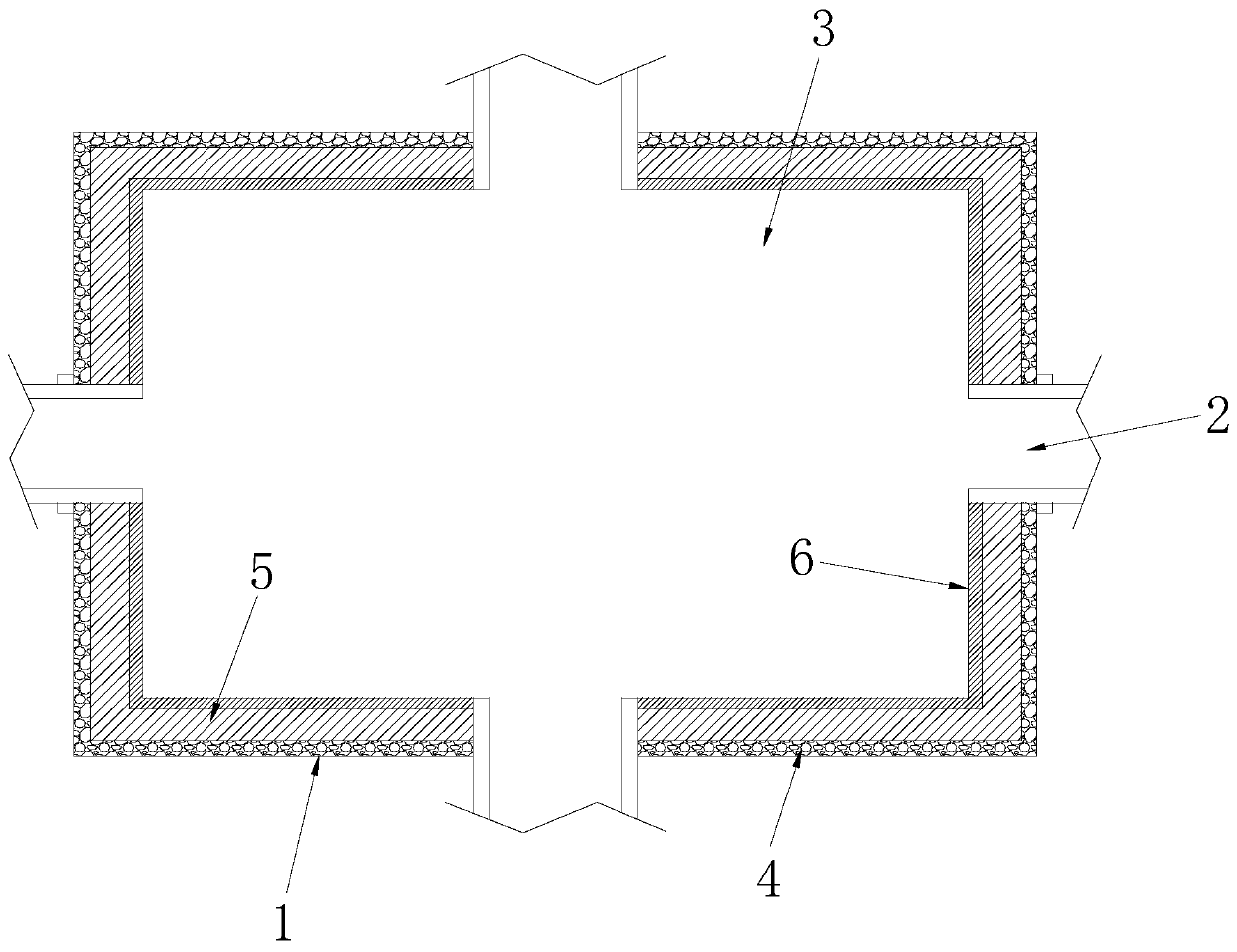
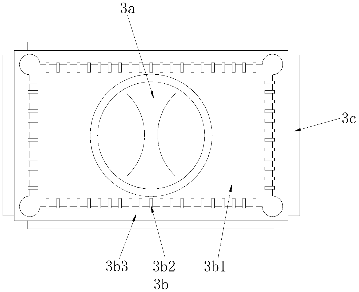
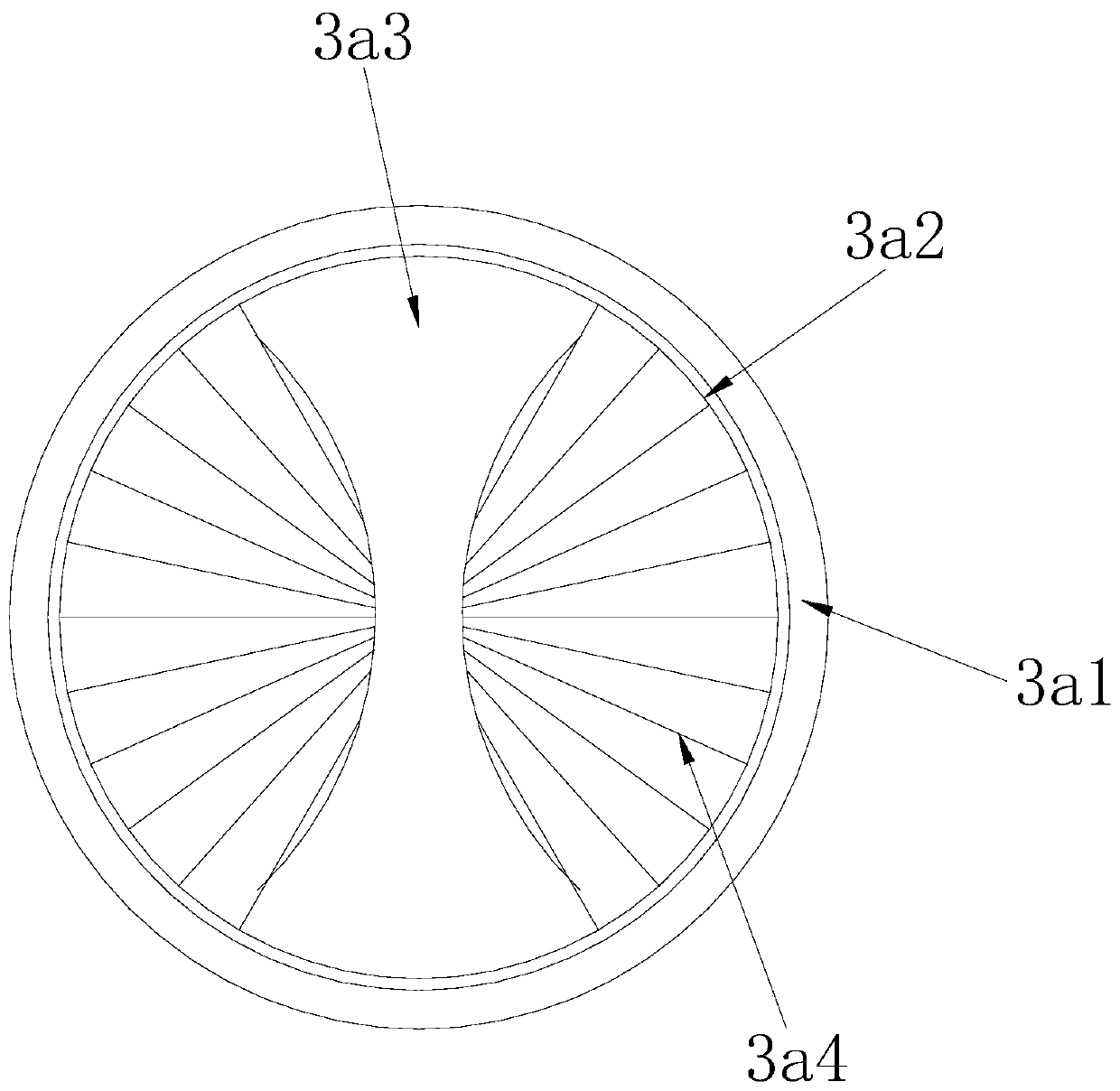
[0028] Such as Figure 1-Figure 3 As shown, the present invention provides a kind of technical scheme of municipal groundwater pollution treatment system:

[0029] Such as Figure 1-Figure 2 Shown, a kind of municipal groundwater pollution treatment system, its structure comprises foundation pit 1, pipeline 2, mud pressing device 3, laying wall 4, waterproof layer 5, putty 6, described pipeline 2 is provided with four groups altogether and is respectively located in On the four side surfaces of the foundation pit 1, the mud pressure device 3 is arranged at the inner and lower part of the foundation pit 1 and is connected by screw bolts. The waterproof layer 5 is arranged on the inner wall of the wall 4, the putty 6 is arranged on the surface of the waterproof layer 5 and connected by pouring and pasting, and the mud pressure device 3 includes a flow stirring structure 3a, a flow diversion structure 3b, and a pressing mechanism 3c , the flow guide structure 3b is arranged on ...

no. 2 example

[0038] Such as figure 1 , figure 2 , Figure 4 , Figure 5 As shown, the present invention provides a kind of technical scheme of municipal groundwater pollution treatment system:

[0039] Such as Figure 1-Figure 2Shown, a kind of municipal groundwater pollution treatment system, its structure comprises foundation pit 1, pipeline 2, mud pressing device 3, laying wall 4, waterproof layer 5, putty 6, described pipeline 2 is provided with four groups altogether and is respectively located in On the four side surfaces of the foundation pit 1, the mud pressure device 3 is arranged at the inner and lower part of the foundation pit 1 and is connected by screw bolts. The waterproof layer 5 is arranged on the inner wall of the wall 4, the putty 6 is arranged on the surface of the waterproof layer 5 and connected by pouring and pasting, and the mud pressure device 3 includes a flow stirring structure 3a, a flow diversion structure 3b, and a pressing mechanism 3c , the flow guide...


PUM


Abstract

The invention discloses a municipal underground water pollution treatment system. The municipal underground water pollution treatment system structurally comprises a foundation pit, a pipeline, a mudpressing device, a built wall, a waterproof layer and putty. The beneficial effects are as follows, a flow stirring structure and a flow guide structure are matched with each other; sludge contained in the sewage is removed; an effective stirring effect is achieved when the slurry is deposited in a foundation pit; the downward drainage effect is achieved on the sludge; therefore, a large amount ofsludge is prevented from being deposited at the bottom in the foundation pit; an oscillation assembly arranged in the pressing mechanism is used in cooperation, further extrusion drying treatment iscarried out on the sludge obtained after flow guiding, then maximum storage treatment is carried out on the sludge, and the dried sludge is used for reinforcing the foundation of the underground watertreatment system.

Description

technical field [0001] The invention relates to the field of sewage treatment systems, more precisely, a municipal groundwater pollution treatment system. Background technique [0002] At the same time as the municipal construction of the city, it is necessary to treat the sewage generated by the municipal administration. Therefore, when configuring the sewage treatment system, due to the large area and large processing capacity of the municipal groundwater pollution treatment system, it is necessary to carry out the basic work manually. The excavation of the pit and the construction and laying of the treatment system. [0003] And because the sewage contains a large amount of silt, when it is collected in one place after flowing with the sewage, it will form sediment at the confluence due to its own gravity, so the storage capacity of the sewage at the confluence is reduced, and it is easy to appear due to the accumulation of silt. Seepage into the ground can easily lead t...

Claims


Application Information

Patent Timeline
Patent Type & Authority Applications(China)
IPC IPC(8): B01F11/00B01F13/10C02F11/121C02F103/06
CPCC02F11/121C02F2103/06C02F2103/001B01F31/44B01F31/449B01F33/83B01F33/83612
Inventor 刘新用
Owner 刘新用
Learn More