Steel plate cutting device

A cutting device and steel plate technology, which is applied in the field of steel plate processing, can solve the problems of complex equipment structure, time-consuming adjustment of cutting angle, etc., and achieve the effect of simple and convenient adjustment, simple structure and low cost

Active Publication Date: 2020-06-09
重庆市荣昌区永世光电设备有限公司
View PDF9 Cites 4 Cited by
  • Summary
  • Abstract
  • Description
  • Claims
  • Application Information

AI Technical Summary

Problems solved by technology

[0004] The present invention intends to provide a steel plate cutting device to solve the problems of complex equipment structure and long time-consuming adjustment of cutting angle existing in the cutting of trapezoidal steel plates in the prior art

Method used


Image

  • Steel plate cutting device
  • Steel plate cutting device
  • Steel plate cutting device

Examples


Embodiment 1

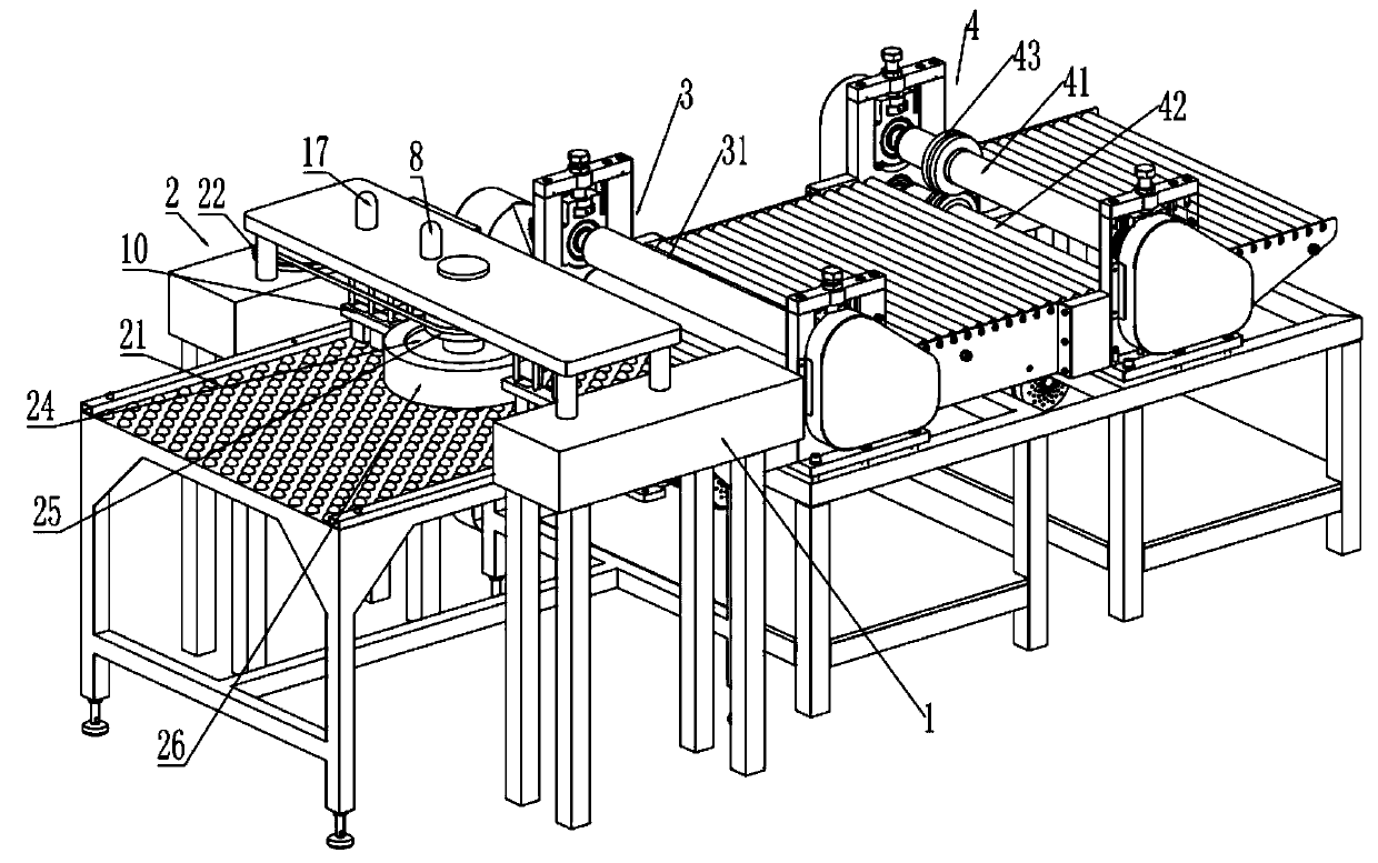
[0039] Embodiment one is basically as attached Figure 1 to Figure 9 Shown:

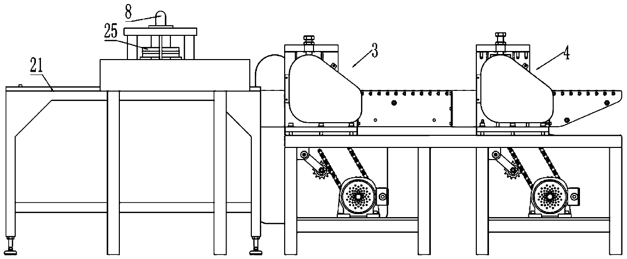
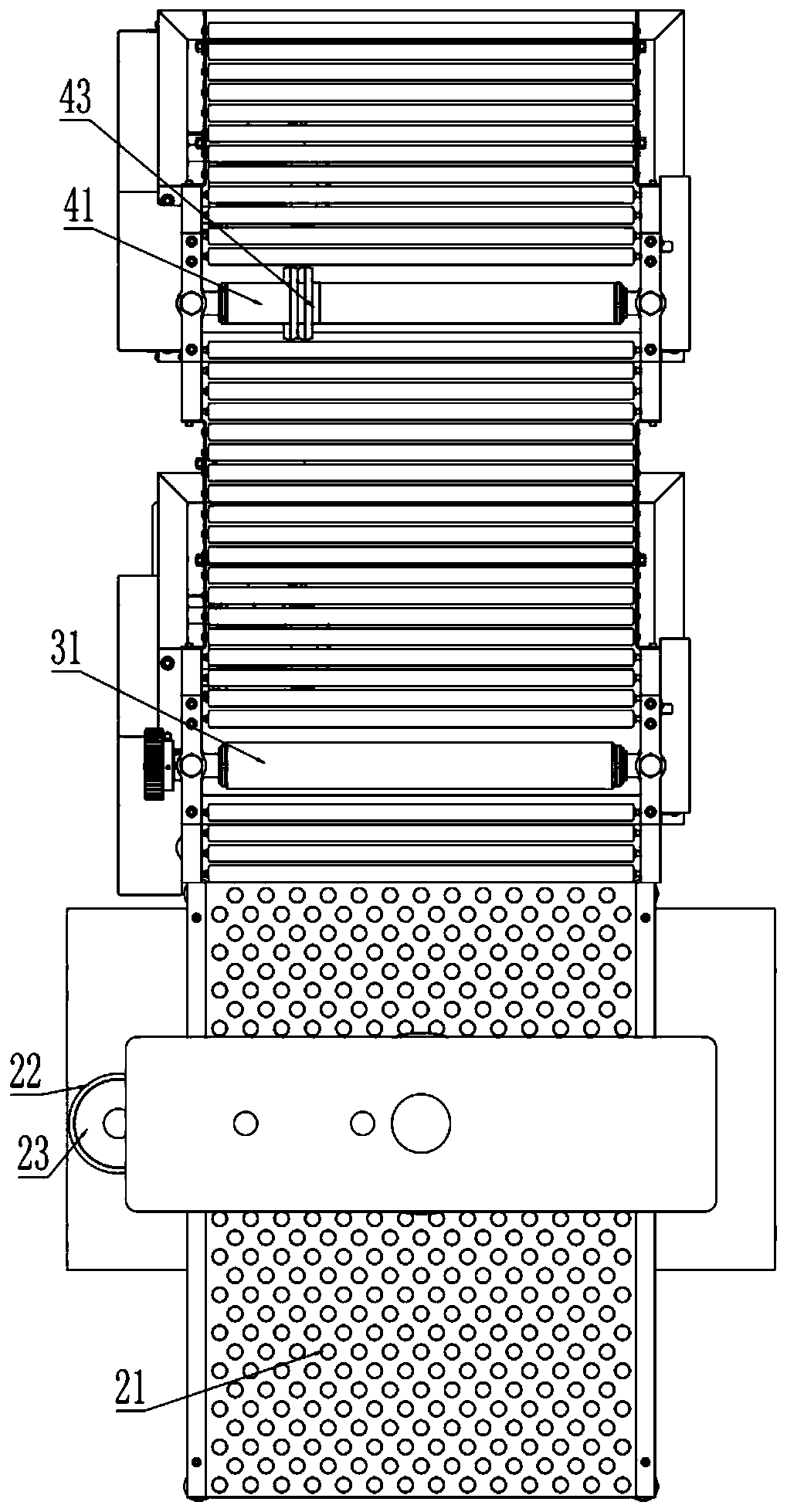
[0040] combine Figure 1 to Figure 3 , steel plate cutting device, including frame 1, pushing mechanism 2, transmission mechanism 3 and cutting mechanism 4, pushing mechanism 2, transmission mechanism 3 and cutting mechanism 4 are all installed on the frame 1, and transmission mechanism 3 includes several rollers And the pair of rollers 31, by the pair of rollers 31, the steel plate on the push-off mechanism 2 will be delivered to the cutting mechanism 4, the cutting mechanism 4 includes an upper turning roller 41 and a lower turning roller 42, both on the upper turning roller 41 and the lower turning roller 42 The key is connected with a rolling shear blade 43, and realizes cutting of the steel plate by the rolling shear blade 43 distributed up and down.

[0041] combine figure 1 , Figure 5 and Figure 6, the tilting mechanism 2 includes a universal ball platform 21, a disc 22, an adjustment d...

Embodiment 2

[0059] combine Figure 10 As shown, on the basis of the first embodiment, the second embodiment adds two pushing units symmetrically along the center of the turntable 24, and each pushing unit includes a cylinder 19 and a pushing plate 20, and the pushing plate 20 is fixedly connected to the At the end of the piston rod, the two flushing plates 20 are parallel to the conveying direction of the transmission mechanism 3, and the two flushing plates 20 are arranged facing each other.

[0060] Before the steel plate is rotated by the tilting mechanism 2, the cylinder 19 of the pushing unit is started first, so that the two pushing plates 20 are close to the steel plate at the same time, and then the steel plate is pushed to the central position of the bottom of the turntable 24, and the steel plate is positioned at the bottom of the turntable 24. After the central position, start the pushing mechanism 2 again to rotate the steel plate at a certain angle, so as to ensure the consis...


PUM


Abstract

The invention relates to the technical field of steel plate machining, and particularly discloses a steel plate cutting device. The device comprises a rack, an inclined pushing mechanism, a conveyingmechanism and a cutting mechanism, the inclined pushing mechanism comprises a universal ball platform and a rotary disc rotationally connected to the rack, the rotary disc is located above the universal ball platform, an electromagnet is slidably connected to the rotary disc, a first elastic piece is connected between the electromagnet and the rotary disc, and the electromagnet can move up and down along the rotary disc. The scheme is used for solving the problems that in the prior art, for trapezoidal steel plate cutting, the equipment structure is complex, and the cutting angle adjustment time is long.

Description

technical field [0001] The invention relates to the technical field of steel plate processing, in particular to a steel plate cutting device. Background technique [0002] At present, most of the trapezoidal steel plates used in the manufacture of conical and polygonal street light poles, square light poles, communication towers, power towers, and other single-stage and multi-stage frustum-shaped towers are first uncoiled and leveled. , cutting or cutting into rectangular plates, and then through longitudinal rolling shear (also known as oblique shear) or shearing machine shearing with a set angle for each veneer, or hot-melt cutting such as plasma and flame, it takes two Only one or even multiple processing can be obtained, the processing technology is complicated, the cost is high, and the efficiency is low. [0003] In the processing of trapezoidal steel plates in the prior art, it is necessary to add a tilting mechanism on the cutting equipment so as to push the steel p...

Claims


Application Information

Patent Timeline
Patent Type & Authority Applications(China)
IPC IPC(8): B23D19/04B23D33/00B23D33/10B23Q1/26B23Q11/00
CPCB23D19/04B23D33/00B23D33/10B23Q1/26B23Q11/0042B23Q11/005
Inventor 赵长刚
Owner 重庆市荣昌区永世光电设备有限公司
Why Eureka
Try Eureka