Vertical drying-and-granulating integrated equipment and working method thereof

A vertical and granulation technology, which is applied to chemical instruments and methods, granulation in static tanks/tanks, dehydration/drying/thickened sludge treatment, etc., can solve the problems of high energy consumption and fixed connections on the top of the shell 1. The motor, the output end of the motor is fixedly connected to the transmission shaft, the left end of the transmission shaft is fixedly connected to the active bevel gear, the upper part of the heating box is fixedly connected to the fixed connecting rod, the middle part of the fixed connecting rod is connected to the longitudinal rotating shaft, and the top of the longitudinal rotating shaft is fixedly connected to the The driven bevel gear, the driven bevel gear is meshed with the driving bevel gear, the bottom of the longitudinal shaft is fixedly connected, and the thermal efficiency is low, so as to achieve the effect of high efficiency

Pending Publication Date: 2020-06-09
青绿智慧(福建省)环保能源科技有限公司
View PDF1 Cites 2 Cited by
  • Summary
  • Abstract
  • Description
  • Claims
  • Application Information

AI Technical Summary

Problems solved by technology

[0003] For example, a vertical pressurized sludge drying treatment device proposed in patent application number 201810125063.8, which includes a housing, a feeding pipe is fixedly connected to the center of the top of the housing, and a cover plate is fixedly connected above the feeding pipe. The upper end of the casing is fixedly connected with a horizontal connecting rod, the inner end of the horizontal connecting rod is fixedly connected with a heating box, the outer side of the heating box is fixedly connected with a number of electric heating tubes, the upper part of the casing 1 is fixedly connected with a motor, and the output end of the motor is fixedly connected with a The transmission shaft, the left end of the transmission shaft is fixedly connected with the active bevel gear, the upper part of the heating box is fixedly connected with the fixed connecting rod, the middle part of the fixed connecting rod is connected with the longitudinal shaft, and the top of the longitudinal shaft is fixedly connected with the driven bevel gear. The movable bevel gear meshes with the driving bevel gear, and the bottom of the longitudinal shaft is fixedly connected with a stirring blade, which is a spiral stirring blade. Although the sludge of this equipment enters the heating box after being sieved through the sieve holes, it is more uniform. Avoid the drying of the sludge on the outside, and the inside is still wet and unevenly dried, but its drying depends entirely on the heat transfer of the electric heating tube to achieve drying. The drying efficiency is low, the energy con

Method used


Image

  • Vertical drying-and-granulating integrated equipment and working method thereof
  • Vertical drying-and-granulating integrated equipment and working method thereof
  • Vertical drying-and-granulating integrated equipment and working method thereof

Examples


Embodiment Construction

[0036] Below in conjunction with embodiment the method of the present invention is described in further detail. It should be noted that the protection scope of the present invention shall include but not be limited to the technical content disclosed in this embodiment.

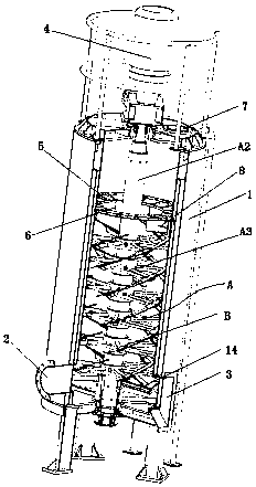
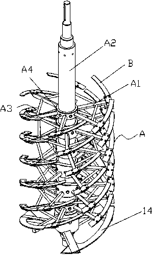
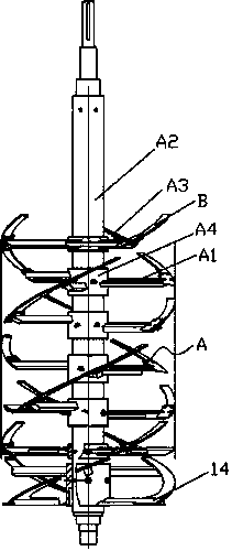
[0037]The vertical drying and granulation integrated equipment of the present invention includes a vertical tank body 1 and a cutter shaft assembly A arranged in the vertical tank body 1, and the cutter shaft assembly A is provided with discontinuous spiral ribbons. The blade B (or a blade with a helical surface in the shape of a broken or continuous belt), is provided with a cutting edge B1 on the lower edge K of each blade B, and each blade B is connected to the cutter shaft through a connecting rod A1 On the assembly A, the intermittent spiral ribbon shape means that the blades on the cutter shaft assembly A are discontinuous, that is, there is a gap in the middle.

[0038] The above-mentioned cutter shaft...


PUM


Abstract

The invention relates to vertical drying-and-granulating integrated equipment and a working method thereof. The vertical drying-and-granulating integrated equipment comprises a vertical tank body anda cutter shaft assembly arranged in the vertical tank body, wherein interrupted spiral strip-shaped blades are distributed on the cutter shaft assembly, a cutting edge is arranged on the lower end edge of each blade, and each blade is connected to the cutter shaft assembly through a connecting rod. The equipment provided by the invention conducts circulated and repeated operations until sludge isdispersed into small-diameter particles and then gradually dries the sludge, so drying and granulating of the sludge are efficiently completed in one piece of equipment, and high efficiency is realized.

Description

Technical field: [0001] The invention relates to equipment for drying treatment of sludge or flocculated sludge, in particular to a vertical drying and granulation integrated equipment and a working method thereof. Background technique: [0002] With the increase of urban population, the amount of urban sewage and sludge that needs to be treated is increasing, and there are also various sludge drying and sludge drying equipment. [0003] For example, a vertical pressurized sludge drying treatment device proposed in patent application number 201810125063.8, which includes a housing, a feeding pipe is fixedly connected to the center of the top of the housing, and a cover plate is fixedly connected above the feeding pipe. The upper end of the casing is fixedly connected with a horizontal connecting rod, the inner end of the horizontal connecting rod is fixedly connected with a heating box, the outer side of the heating box is fixedly connected with a number of electric heating ...

Claims


Application Information

Patent Timeline
IPC IPC(8): C02F11/13C02F11/00B01J2/10
CPCB01J2/10C02F11/00C02F11/13
Inventor 刘建津
Owner 青绿智慧(福建省)环保能源科技有限公司
Why Eureka
Try Eureka