Constraining steel pipe lap joint structure for vertical prefabricated component
A technology of prefabricated components and lap joints, applied in building components, building structures, structural elements, etc., can solve the problems of difficult installation, difficult to ensure construction quality, and inability to fully exert the force transmission performance of lap joints. Small, easy to ensure construction quality, dense filling material effect
- Summary
- Abstract
- Description
- Claims
- Application Information
AI Technical Summary
Problems solved by technology
Method used
Image

Examples
Embodiment 1
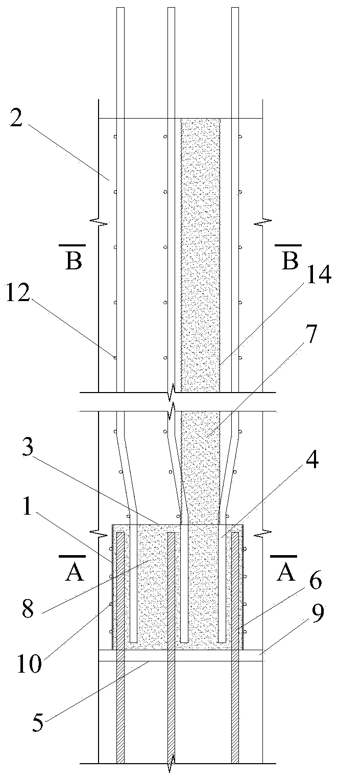
[0027] see figure 1 , a constrained steel pipe lap connection structure for prefabricated vertical members according to Embodiment 1 of the present invention, used for the connection of longitudinal steel bars in edge members of prefabricated concrete shear walls, including constrained steel pipes located at the inner bottom of the upper prefabricated member 2 1. Steel mesh or steel wire mesh 3 is fixed on the top of the constrained steel pipe 1, structural stirrups 10 are arranged on the outside of the constrained steel pipe 1, the longitudinal reinforcement 4 at the bottom of the upper prefabricated member 2 and the connecting longitudinal reinforcement exposed outside the top surface 5 of the lower floor The ribs 6 are all inserted into the restraining steel pipe 1 and overlapped with each other; the joint 9 is set between the upper prefabricated component 2 and the top surface 5 of the lower floor, and the height of the joint 9 is 20-50 mm; the restraining steel pipe 1 is f...
Embodiment 2
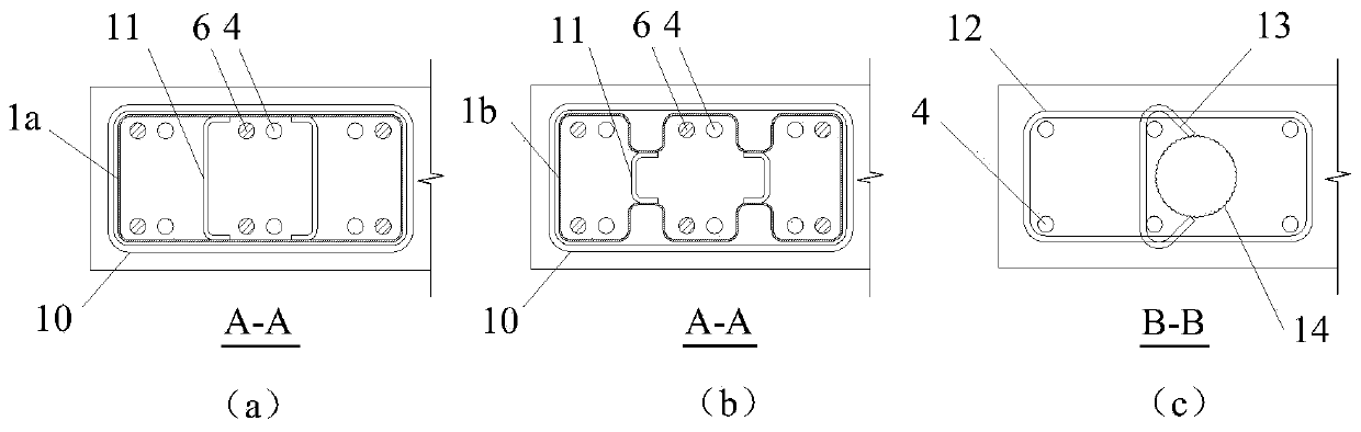
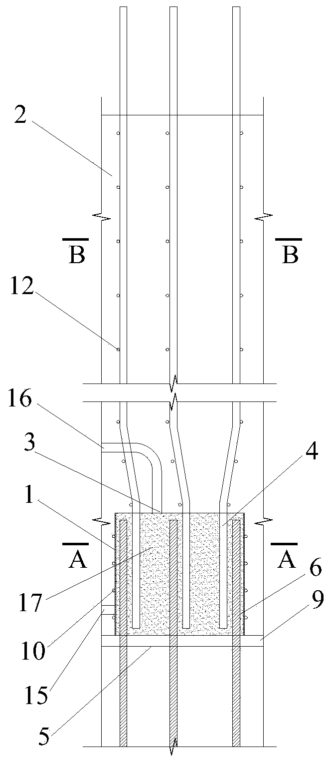
[0035] see image 3 , a constrained steel pipe lap connection structure for prefabricated vertical members according to Embodiment 2 of the present invention, which is used for the connection of longitudinal steel bars in edge members of prefabricated concrete shear walls. The difference from Embodiment 1 is that in this embodiment, ultra-high performance concrete (UHPC, Ultra-High Performance Concrete) is poured into the restrained steel pipe 1 through the grouting hole 15 and the grouting hole 16 reserved at the bottom of the upper prefabricated component 2. ) or high-strength cement-based grouting material 17, replace the mode of pouring concrete in embodiment 1 with this; Constrained steel pipe 1 can also adopt welded combination steel pipe 1c (such as Figure 4 shown); when the restraint steel pipe 1 adopts a rectangular steel pipe 1a or a special-shaped steel pipe 1b, the tie bar 11 in the restraint steel pipe can also be replaced by a partition of the same height as the...
Embodiment 3
[0037] A kind of restrained steel pipe lap connection structure used for prefabricated vertical members in embodiment 3 of the present invention is used for the connection of longitudinal steel bars in prefabricated concrete columns, which is the same as the connection structure in embodiment 1 (such as figure 1 shown), except that: see Figure 5 , the restrained steel pipe of this embodiment (such as Figure 5 As shown in (a) and (b), 1a and 1b are the tie bars 011 set in the rectangular steel pipe and special-shaped steel pipe respectively), and the tie bars 013 in the range of the upper prefabricated column of the constrained steel pipe (such as Figure 5 Shown in (c)) are two-way layout. The distance from the outer edge of the rectangular steel pipe 1a or special-shaped steel pipe 1b to the edge of the prefabricated component is 25-40mm, and the wall thickness of the steel pipe is 1-4mm.
PUM
| Property | Measurement | Unit |
|---|---|---|
| Spacing | aaaaa | aaaaa |
| Size | aaaaa | aaaaa |
| Height | aaaaa | aaaaa |
Abstract
Description
Claims
Application Information
 - R&D
- Intellectual Property
- Life Sciences
- Materials
- Tech Scout
- Unparalleled Data Quality
- Higher Quality Content
- 60% Fewer Hallucinations
Browse by: Latest US Patents, China's latest patents, Technical Efficacy Thesaurus, Application Domain, Technology Topic, Popular Technical Reports.
© 2025 PatSnap. All rights reserved.Legal|Privacy policy|Modern Slavery Act Transparency Statement|Sitemap|About US| Contact US: help@patsnap.com