Siphon pump

A siphon tube and pump core technology, applied in the field of siphon tube pumps, can solve the problems of high energy consumption and unfavorable popularization and use, and achieve the effect of low emission and reduced construction and maintenance costs

Active Publication Date: 2020-06-09
HAINAN GUANGYUANLONG ENERGY SAVING TECH SERVICE
View PDF6 Cites 6 Cited by
  • Summary
  • Abstract
  • Description
  • Claims
  • Application Information

AI Technical Summary

Problems solved by technology

The system can be flexibly used for farmland irrigation, providing clean drinking water for humans and animals, developing courtyard economy, beautifying parks, environment and desert control, etc. without any external energy. Large energy consumption is not conducive to popularization and use

Method used


Image

  • Siphon pump
  • Siphon pump
  • Siphon pump

Examples


Embodiment 1

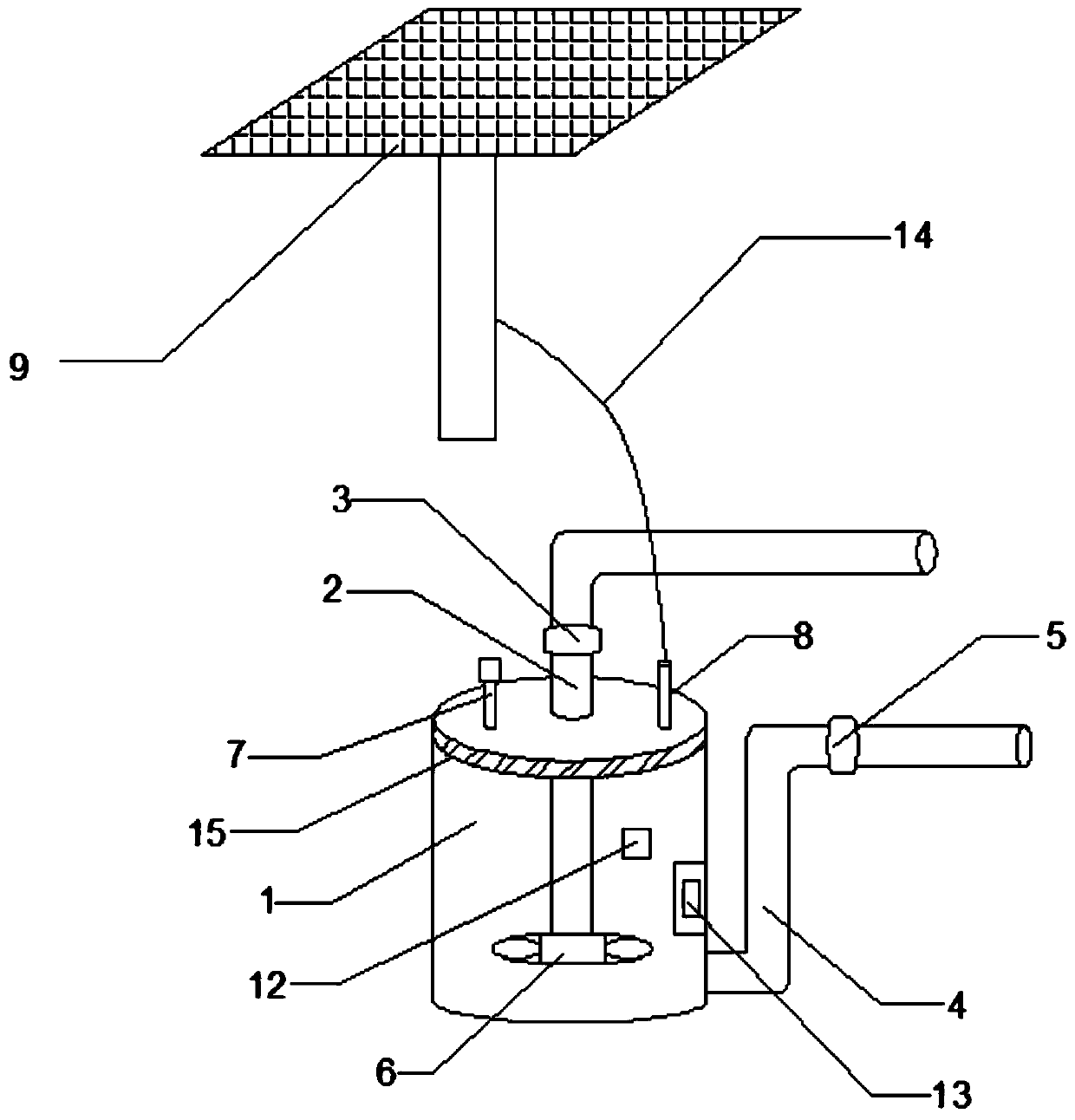
[0019] See figure 1 , A siphon pump comprising an outer tube body 1, a pump core impeller 6, a water level controller 13, a water stop valve 3, a water supplement valve 5, and a water level sensor 12. The outer tube body 1 is a hollow structure, and the outer tube body 1. A water diversion pipe 2 is provided on the top, and the water diversion pipe 2 extends to the inside of the outer tube body 1, a water stop valve 3 is provided on the water diversion pipe 2, and the pump core impeller 6 is arranged at the end of the water diversion pipe 2. The top of the outer tube body 1 is provided with a first exhaust valve 7 which is connected to the exhaust pipe, and the bottom of the outer tube body 1 is provided with a water inlet pipe 4 which extends to the water source Where, the water inlet pipe 4 is provided with a water supply valve 5, the water level sensor 12 and the water level controller 13 are both arranged inside the outer pipe body 1, the water level sensor 12, the water sto...

Embodiment 2

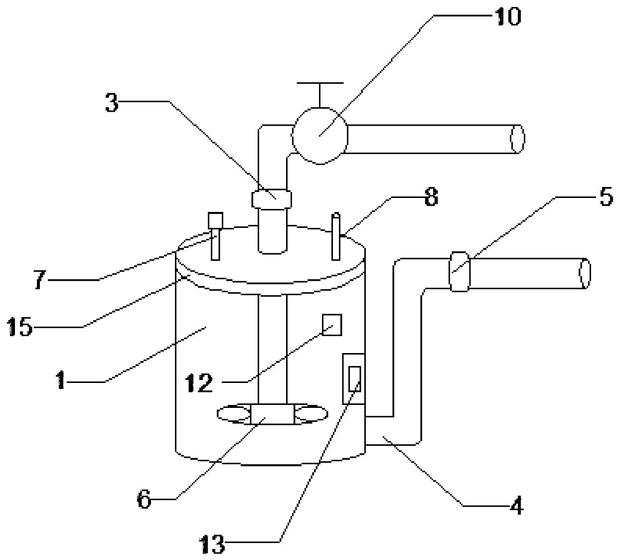
[0027] The difference between this embodiment 2 and embodiment 1 is that a second exhaust valve 10 is provided on the water introduction pipe 2, and the second exhaust valve 10 is provided at the outlet 810 end of the water stop valve 3, and The second exhaust valve 10 is connected to the water pipe 2, and the second exhaust valve 10 is connected to the water level controller 13 via a wire. When the water stop valve 3 needs to be opened, the water level controller 13 preferentially opens the second row The gas valve 10, the second exhaust valve 10 extracts the gas in the water pipe 2 to reduce the gas pressure inside the pipe.

Embodiment 3

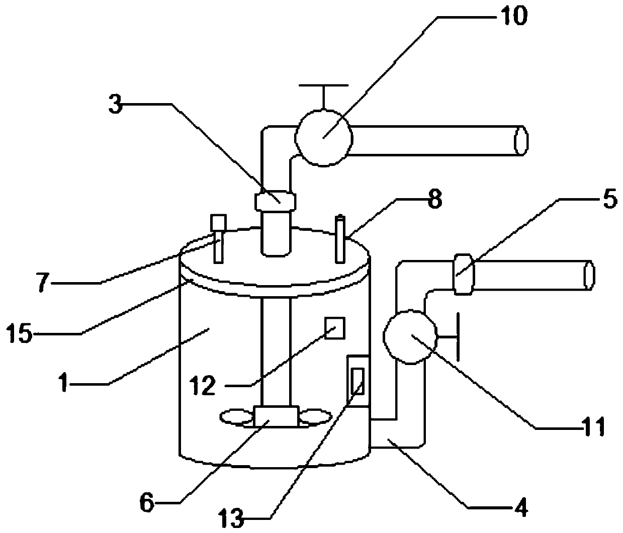
[0029] The difference between this embodiment 3 and embodiment 2 is that the water inlet pipe 4 is provided with a third exhaust valve 11, the third exhaust valve 11 is provided at the inlet end of the water make-up valve 5, and the third row The air valve 11 is connected with the water make-up valve 5 and the water inlet pipe 4 in sequence. The third exhaust valve 11 is connected with a signal of the water level controller 13 through a wire. When the water stop valve 3 needs to be opened for water intake, the water level controller 13 is turned on first The third exhaust valve 11 extracts gas from the water inlet pipe 4 and reduces the air pressure in the water inlet pipe 4.


PUM


Abstract

The invention provides a siphon pump which comprises an outer pipe body, a pump core impeller, a water level controller, a water stop valve, a water supplementing valve and a water level sensor, wherein the outer pipe body is of a hollow structure; the top of the outer pipe body is provided with a water guide pipe; the water guide pipe extends to the inside of the outer pipe body; the water stop valve is arranged on the water guide pipe; the pump core impeller is arranged at the tail end of the water guide pipe; a first exhaust valve used for exhausting gas inside the outer pipe body is arranged at the top of the outer pipe body; a water inlet pipe is arranged at the bottom of the outer pipe body; the water inlet pipe extends to a water source; the water supplementing valve is arranged onthe water inlet pipe; both the water level sensor and the water level controller are arranged inside the outer pipe body; and the water level sensor, the water stop valve, the pump core impeller and the water supplementing valve are all connected with the water level controller through signals.

Description

Technical field [0001] The invention relates to the technical field of water pumps, in particular to a siphon pump. Background technique [0002] For a long time, how to solve the problem of water pumping and water supply in mountainous areas, arid areas, grassland pastures, and desertified areas at the energy level has been a technical problem that has plagued the development of agriculture and animal husbandry and ecological construction at home and abroad. In recent years, photoelectric water control technology has catered to large-scale farmland, grassland, desert and other demand markets, and can be widely used in remote areas without electricity or electricity shortages for humans and livestock, farmland irrigation, desert governance, water system interconnection, pipe network interconnection, etc. . The system can be flexibly used for farmland irrigation, providing clean drinking water for humans and animals, developing courtyard economy, beautifying parks, environment an...

Claims


Application Information

Patent Timeline
Patent Type & Authority Applications(China)
IPC IPC(8): F04F10/00
CPCF04F10/00
Inventor 周学东
Owner HAINAN GUANGYUANLONG ENERGY SAVING TECH SERVICE
Why Eureka
Try Eureka