

Hydrogen filling system
A filling system and filling device technology, applied in the field of hydrogen filling system, can solve the problems of high cost of liquid hydrogen and great influence of the initial state of the tank, etc.
- Summary
- Abstract
- Description
- Claims
- Application Information
AI Technical Summary
Problems solved by technology
Method used
Image

Examples
Embodiment 1
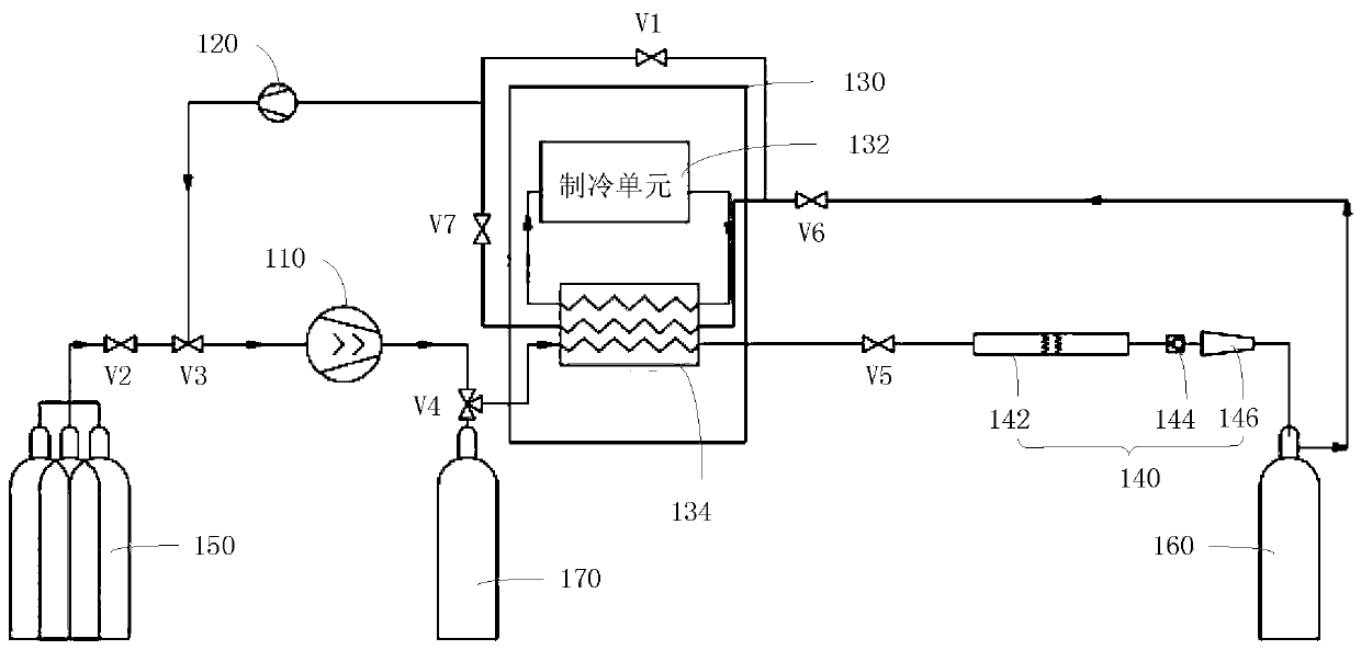
[0032] Such as figure 2 As shown, a hydrogen filling system in one embodiment includes a booster device 110, a circulation device 120, a refrigeration device 130, a first valve V1, a filling device 140 and a measurement and control device (not shown).
[0033] The refrigeration device 130 includes a refrigeration unit 132 and a heat exchanger 134 . The heat exchanger 134 includes a first heat exchange pipeline (not marked in the figure), a second heat exchange pipeline (not marked in the figure) and a cooling medium pipeline (not marked in the figure). The outlet of the refrigeration unit 132 is connected with the inlet of the cooling medium pipeline. The outlet of the cooling medium pipeline is connected with the inlet of the refrigeration unit 132.
[0034] The inlet of the supercharging device 110 is used to connect with the hydrogen storage device 150, the outlet of the supercharging device 110 is connected to the inlet of the first heat exchange pipeline, the outlet of...
Embodiment 2
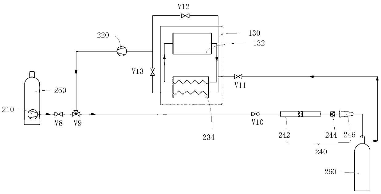
[0058] Such as image 3 As shown, a hydrogen filling system in one embodiment includes a booster device 210, a circulation device 220, a refrigeration device 230, a filling device 240, and a measurement and control device (not shown).
[0059] The inlet of the supercharging device 210 is used to connect to the hydrogen storage device 250, the outlet of the supercharging device 210 is connected to the inlet of the filling device 240, the outlet of the filling device 240 is used to connect to the inlet of the vehicle-mounted hydrogen storage container 260, and the refrigeration device The inlet of 230 is used to connect with the outlet of on-board hydrogen storage container 260 , the outlet of refrigeration device 230 is connected with the inlet of circulation device 220 , and the outlet of circulation device 220 is connected with the inlet of filling device 240 .
[0060] The pressurizing device 210, the circulation device 220, the refrigeration device 230 and the filling devic...
PUM
 Abstract
Description
Claims
Application Information