Furnace tube structure of tungsten-molybdenum calcination or reduction rotary furnace

A technology of rotary furnace and furnace tube, which is applied in the direction of rotary drum furnace, furnace, furnace charge, etc., which can solve the problems of low yield of powder materials, large temperature difference of furnace tube, unstable product quality, etc., and achieve sufficient reaction and concentrated particle size distribution , the effect of uniform temperature

Pending Publication Date: 2020-06-09
赣州奥途科技有限公司
View PDF0 Cites 1 Cited by
  • Summary
  • Abstract
  • Description
  • Claims
  • Application Information

AI Technical Summary

Problems solved by technology

[0006] Aiming at the deficiencies of the prior art, the object of the present invention is to provide a furnace tube structure of a tungsten-molybdenum calcination or reduction rotary furnace, which aims to solve the problem of large temperature difference inside the furnace tube, unstable product quality, The technical problem of low powder material yield; the furnace tube structure adopts the double-layer furnace tube structure and the heating device fixedly installed in the h

Method used


Image

  • Furnace tube structure of tungsten-molybdenum calcination or reduction rotary furnace
  • Furnace tube structure of tungsten-molybdenum calcination or reduction rotary furnace
  • Furnace tube structure of tungsten-molybdenum calcination or reduction rotary furnace

Examples


Example Embodiment

[0025] Example 1

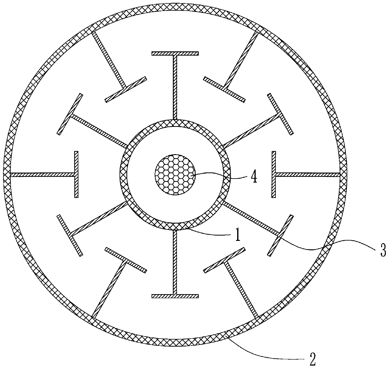
[0026] This specific embodiment is a rotary kiln used for tungsten and molybdenum calcination or reduction. The other parts of the rotary kiln are consistent with the current structure. Only the furnace tube structure is a non-current single-layer structure, but a double-layer coaxial hollow cylindrical structure , The structure diagram of the furnace tube structure is as figure 1 As shown, and on the outer bracket of the double-layer furnace tube, an electric heating device is also fixedly installed. The furnace tube structure includes an inner furnace tube wall and an outer furnace tube wall that are fixedly connected to each other, an inner furnace tube wall and an outer furnace tube wall The two can be fixedly connected by welding a fixed connecting rod, and the two ends between the inner furnace tube wall and the outer furnace tube wall are connected and sealed by a sealing plate, and a feed port is provided at one end , There is a discharge port at the ot...

Example Embodiment

[0027] Example 2

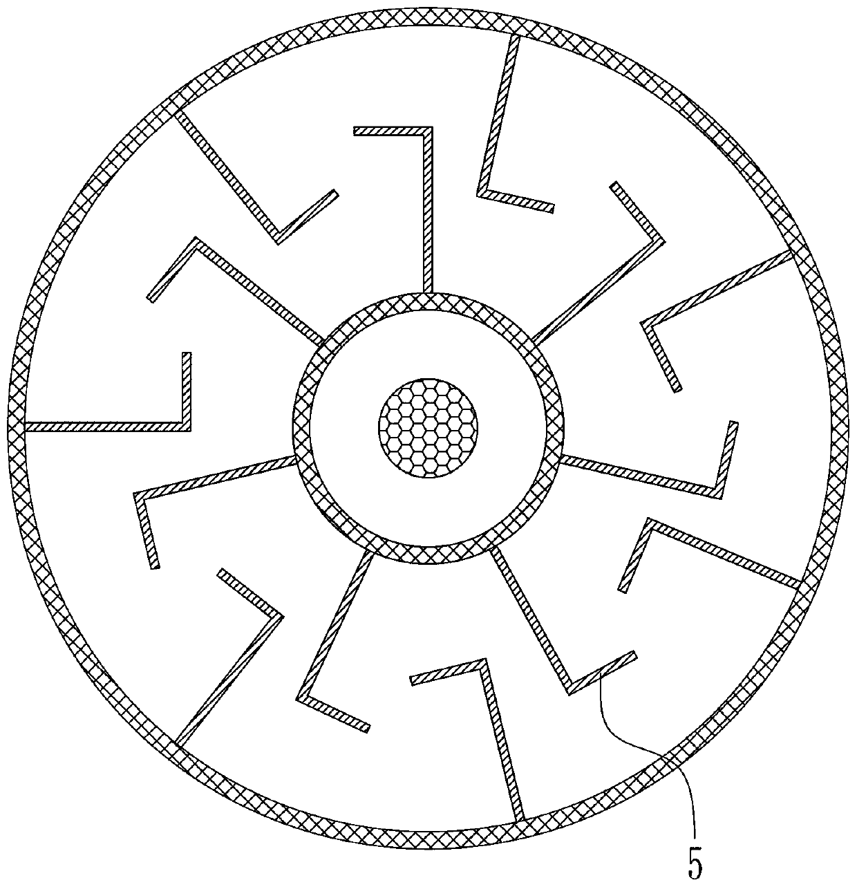
[0028] This specific embodiment is a rotary kiln used for tungsten and molybdenum calcination or reduction. The other parts of the rotary kiln are consistent with the current structure. Only the furnace tube structure is a non-current single-layer structure, but a double-layer coaxial hollow cylindrical structure , The structure diagram of the furnace tube structure is as figure 2 As shown, and on the outer bracket of the double-layer furnace tube, an electric heating device is also fixedly installed. The furnace tube structure includes an inner furnace tube wall and an outer furnace tube wall that are fixedly connected to each other, an inner furnace tube wall and an outer furnace tube wall The two can be fixedly connected by welding a fixed connecting rod, and the two ends between the inner furnace tube wall and the outer furnace tube wall are connected and sealed by a sealing plate, and a feed port is provided at one end , There is a discharge port at the o...

Example Embodiment

[0029] Example 3

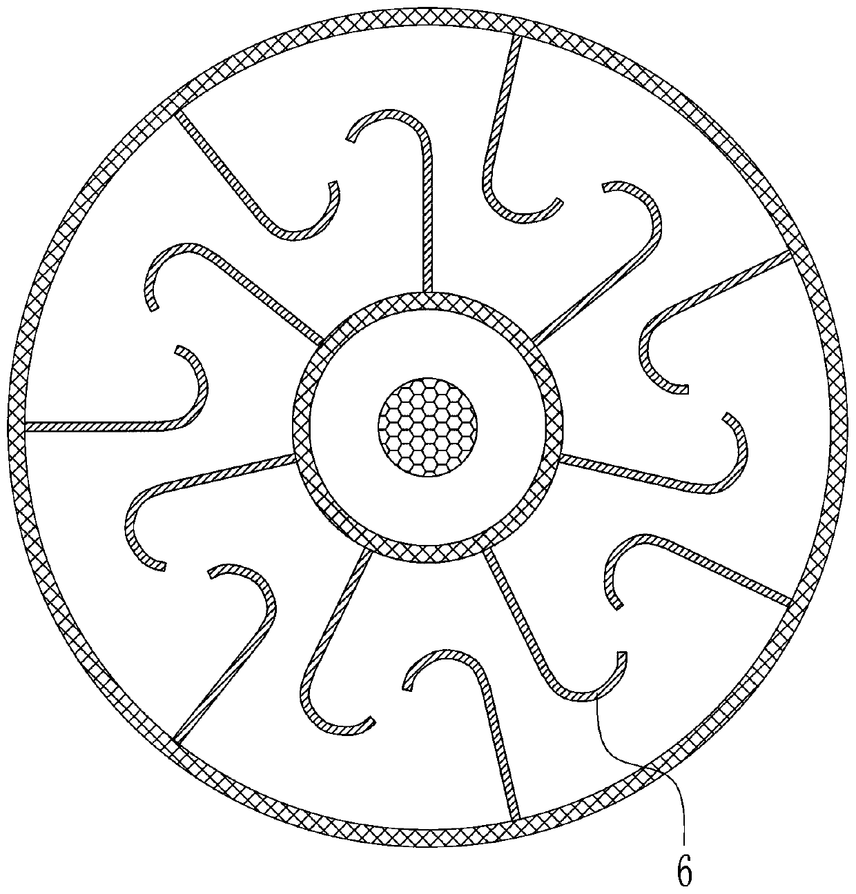
[0030] This specific embodiment is a rotary kiln used for tungsten and molybdenum calcination or reduction. The other parts of the rotary kiln are consistent with the current structure. Only the furnace tube structure is a non-current single-layer structure, but a double-layer coaxial hollow cylindrical structure , The structure diagram of the furnace tube structure is as image 3 As shown, and on the outer bracket of the double-layer furnace tube, an electric heating device is also fixedly installed. The furnace tube structure includes an inner furnace tube wall and an outer furnace tube wall that are fixedly connected to each other, an inner furnace tube wall and an outer furnace tube wall The two can be fixedly connected by welding a fixed connecting rod, and the two ends between the inner furnace tube wall and the outer furnace tube wall are connected and sealed by a sealing plate, and a feed port is provided at one end , There is a discharge port at the o...


PUM


Abstract

The invention discloses a furnace tube structure of a tungsten-molybdenum calcination or reduction rotary furnace. The furnace tube structure aims to solve the technical problems of large temperaturedifference, unstable product quality and low powder material yield in a furnace tube in existing rotary furnace processing. The furnace tube structure is a double-layer coaxial hollow tubular structure and comprises an inner furnace tube wall and an outer furnace tube wall which are fixedly connected with each other, a feeding opening is formed in one end between the inner furnace tube wall and the outer furnace tube wall, a discharging opening is formed in the other end between the inner furnace tube wall and the outer furnace tube wall, a heating space for tungsten-molybdenum calcination orreduction is formed between the inner furnace tube wall and the outer furnace tube wall, and a plurality of material-blocking rib plates perpendicular to the axial direction are correspondingly and fixedly installed on the inner furnace tube wall and the outer furnace tube wall in the heating space in the axial direction in a uniform distribution mode. According to the furnace tube structure of the tungsten-molybdenum calcination or reduction rotary furnace, an inner furnace tube and an outer furnace tube are heated at the same time, the temperature uniformity and sufficient reaction of powdermaterials are effectively ensured, uniformity and stability of the product quality are ensured, and the powder material yield is improved.

Description

technical field [0001] The invention belongs to the field of tungsten-molybdenum chemical metallurgical treatment equipment, in particular to a furnace tube structure of a tungsten-molybdenum calcining or reduction rotary furnace. Background technique [0002] Rotary furnace is a kind of thermal processing equipment for calcining, roasting or drying granular and powdery materials. It is widely used in various chemical and metallurgical treatments. The characteristic of rotary furnace is that its furnace tube will be connected to a motor to drive its rotation, so it is called It is a rotary furnace; at the same time, according to its different processing needs, the structure of the rotary furnace will also undergo certain changes accordingly. [0003] In the field of tungsten and molybdenum processing, the rotary furnace includes a rotary tube calciner and a rotary tube reduction furnace. The rotary tube calciner can be used to heat and calcinate ammonium paratungstate (or am...

Claims


Application Information

Patent Timeline
IPC IPC(8): F27B7/10F27B7/16F27B7/22F27B7/34
CPCF27B7/10F27B7/162F27B7/22F27B7/34F27M2003/03F27M2003/165
Inventor 袁逢盛杨贵彬王浩胜王文圣李奕福
Owner 赣州奥途科技有限公司
Why Eureka
Try Eureka