
Radar sensor

A radar sensor and radar technology, which is applied in the direction of instruments, measuring devices, radio wave measurement systems, etc., can solve the problems that radar loses the ability to track real targets, the detection ability affects radar sensors, and reduces the signal-to-noise ratio of radar detection, etc., to achieve freedom High precision, good economy, and the effect of suppressing radiation interference

Pending Publication Date: 2020-06-09
WUXI WEIFU HIGH TECH CO LTD
View PDF0 Cites 3 Cited by
  • Summary
  • Abstract
  • Description
  • Claims
  • Application Information

AI Technical Summary

Problems solved by technology

[0003] With the development of automobile electrification and intelligence, radar is becoming more and more popular. At the same time, between radar and other electronic components in the car, between radar and radar, between radar and road environment, etc. The electromagnetic environment will become more and more complex, which may reduce the signal-to-noise ratio of radar detection, resulting in a decrease in the probability of target detection, and will also cause the victim vehicle radar to lose the ability to track real targets
The current millimeter-wave radar sensor mainly adopts signal waveform design to avoid interference technology, but the hardware cannot completely realize the shielding of external electromagnetic environment interference, especially the radar antenna board is mostly a PCB board with an RF chip and an antenna array, and external signals are easily transmitted. The radome radiates to the antenna board to interfere with the radar system. With the rapid increase of radar sensors, the radar will face unintentional or intentional electromagnetic environment interference. The detection ability, robustness, and anti-interference ability of automotive radar will seriously affect the radar sensor function. Applications

Method used


Image

  • Radar sensor
  • Radar sensor

Examples


Embodiment Construction

[0028] The present invention will be further described below in conjunction with specific drawings and embodiments.

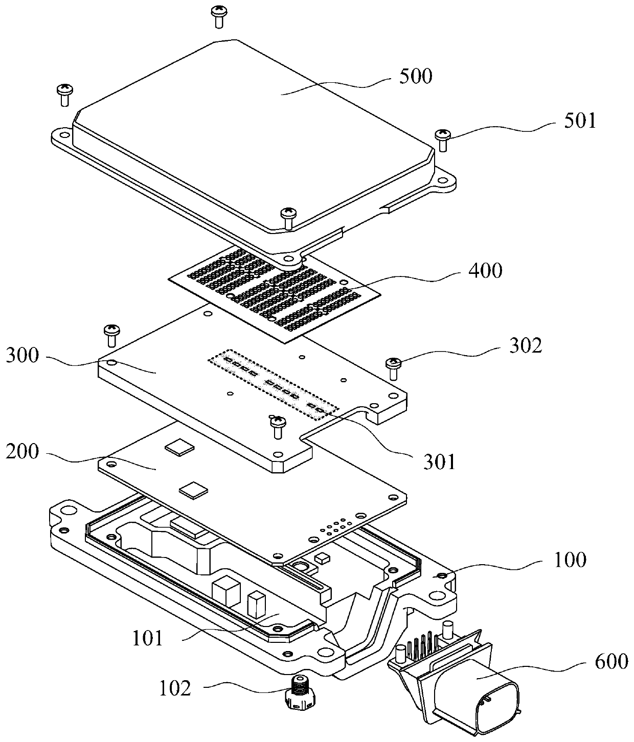
[0029] An embodiment of the present invention proposes a radar sensor, including: a radar rear cover 100, a signal processing circuit board 200, an antenna carrier board 300, an antenna circuit board 400, a radar front cover 500, and an external connector 600;

[0030] The signal processing circuit board 200 is installed on the radar rear cover 100, and the radar rear cover 100 is made of a metal material, usually formed by aluminum alloy die-casting; After the wire copper foil is in contact with the radar rear cover 100 and the separating ribs, several independent electromagnetic shielding cavities 101 are formed between the signal processing circuit board 200 and the radar rear cover 100; The shielded circuits are respectively located in separate electromagnetic shielding cavities between the radar rear cover 100 and the signal processing board 200; the exter...


PUM


Abstract

The invention provides a radar sensor which comprises a radar rear cover, a signal processing circuit board, an antenna carrier plate, an antenna circuit board, a radar front cover and an external connector. The signal processing circuit board is installed on the radar rear cover, and a plurality of independent electromagnetic shielding cavities are formed between the signal processing circuit board and the radar rear cover. Circuits needing mutual electromagnetic shielding on the lower layer of the signal processing circuit board are respectively positioned in the independent electromagneticshielding cavities between the radar rear cover and the signal processing board; the antenna carrier plate is installed on the signal processing circuit board, and an electromagnetic shielding cavityis formed between the antenna carrier plate and the signal processing circuit board. The circuit on the upper layer of the antenna carrier plate is positioned in the electromagnetic shielding cavity between the signal processing circuit board and the antenna carrier plate; a waveguide through hole is formed in the antenna carrier plate; the antenna circuit board is installed on the antenna carrierplate. The signal processing circuit board feeds power to the antenna circuit board through the antenna carrier plate waveguide through hole. The radar sensor can avoid electromagnetic interference between internal circuits and shield external electromagnetic interference.

Description

technical field [0001] The invention relates to the technical field of millimeter-wave radar systems, in particular to a long-distance millimeter-wave radar sensor. Background technique [0002] With the continuous growth of automobile safety standards, automobile electronic level and people's demand for driving safety, the advanced driver assistance system (ADAS) technology with active safety technology has shown a rapid development trend in recent years. Most road traffic accidents occur due to human error. ADAS can effectively prevent and reduce the occurrence of traffic accidents by reminding drivers to pay attention to and helping them solve various problems. As the main sensor in the application of advanced driving assistance systems, millimeter-wave radar detects the relative speed, distance and angle information of obstacles by sending and receiving electromagnetic waves, and can play functions such as cruise, collision avoidance, auxiliary lane change, and blind spo...

Claims


Application Information

Patent Timeline
Patent Type & Authority Applications(China)
IPC IPC(8): G01S7/28G01S7/36G01S7/02
CPCG01S7/28G01S7/36G01S7/023G01S7/027
Inventor 屈操闫红宇李刚
Owner WUXI WEIFU HIGH TECH CO LTD
Learn More