Machine tool driving type retractable cutter and method for machining differential mechanism shell by using same

A driving and cutting tool technology, applied in metal processing equipment, metal processing mechanical parts, manufacturing tools, etc., can solve the problems of low processing accuracy, high price, and expensive structure, so as to reduce positional accuracy deviation and improve product processing accuracy. , the effect of reducing investment costs

Active Publication Date: 2020-06-12
山东沪金精工科技股份有限公司
View PDF7 Cites 3 Cited by
  • Summary
  • Abstract
  • Description
  • Claims
  • Application Information

AI Technical Summary

Problems solved by technology

[0003] 1. Using the countersink machining method, the planetary gear shaft hole is pre-processed, and the pull rod is inserted from both sides through the processed hole to withstand the countersink, and the workpiece moves with the fixture to process the inner spherical surface. The countersink is used for machining. The main disadvantages are: the shape of the tool is complicated, it needs to be specially ordered, the service life is low, and the price is high
It is inconvenient for the tool to enter and exit the differential case, and a special tool holding mechanism is required. The dimensional accuracy of the inner spherical surface depends on the tool accuracy. The processing equipment needs to use a special machine tool, or use an ordinary lathe to modify it;
[0004] 2. It is processed by multi-axis CNC lathe. The tool holder of multi-axis CNC machine tool can do complex plane movement. Through the processed hole, the tool is inserted into the differential case, and the inner spherical surface is processed. Multi-axis CNC lathe processing The main features of the inner spherical surface: good processing quality and high efficiency, but need to buy imported machine tools, which are expensive;
[0005] 3. Using the swinging tool processing method, the workpiece needs to be rotated when a special machine tool is used for processing. The tie rod equipped with the tool enters the differential case through the hole that has been added. Pull out the rod and make a circular motion around the center of the circle, thereby adding L to the inner spherical surface. When using the swinging tool method to process the inner spherical surface, the center of the tool’s circular arc movement must coincide with the center of the SR51 sphere, and the dimensional accuracy depends on the tool tip to the tool rotation center. distance, cannot compensate for tool tip wear
[0006] Most of the above methods and equipment have the disadvantages of expensive structure and low processing accuracy

Method used


Image

  • Machine tool driving type retractable cutter and method for machining differential mechanism shell by using same
  • Machine tool driving type retractable cutter and method for machining differential mechanism shell by using same
  • Machine tool driving type retractable cutter and method for machining differential mechanism shell by using same

Examples


Embodiment 1

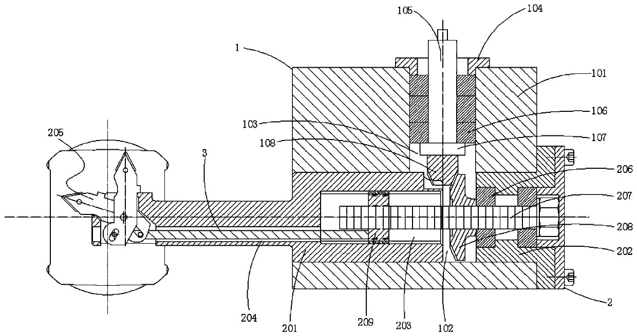
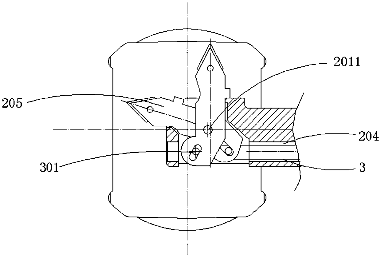
[0030] see figure 1 , 2 , a machine-driven telescopic tool, comprising a power turret 1 and a power tool holder 2, characterized in that: the inside of the power turret 1 is connected to the outside of the power tool holder 2;

[0031] The power turret 1 includes a turret housing 101, an installation port 102, a power port 103, a mounting ring 104, a worm 105, a first bearing 106 and a limit ring 107, and the exterior of the power turret 1 is provided with The turret housing 101, the bottom of the turret housing 101 is provided with a left and right through installation port 102, and the upper end of the turret housing 101 is provided with a vertical power port 103, the power port 103 communicates with the installation port 102, the upper opening position of the power port 103 is fixedly installed with a mounting ring 104, and a worm 105 is rotatably connected inside the mounting ring 104, and the bottom end of the worm 105 is a transmission gear part, Three first bearings 1...

Embodiment 2

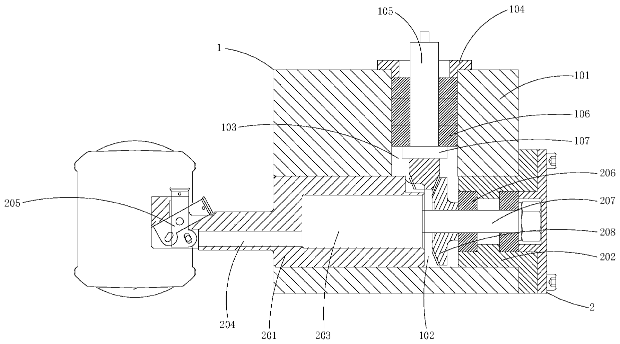
[0034] see Figure 3-5 , a machine tool driven retractable tool, comprising a power turret 1 and a power tool holder 2, characterized in that: the inside of the power turret 1 is connected to the outside of the power tool holder 2;

[0035] The power turret 1 includes a turret housing 101, an installation port 102, a power port 103, a mounting ring 104, a worm 105, a first bearing 106 and a limit ring 107, and the exterior of the power turret 1 is provided with The turret housing 101, the bottom of the turret housing 101 is provided with a left and right through installation port 102, and the upper end of the turret housing 101 is provided with a vertical power port 103, the power port 103 communicates with the installation port 102, and the upper opening position of the power port 103 is fixedly installed with a mounting ring 104, and a worm 105 is rotatably connected inside the mounting ring 104, and the bottom end of the worm 105 is a transmission gear part, Three first be...

Embodiment 3

[0039] see Figure 3-5 , a machine tool driven retractable tool, comprising a power turret 1 and a power tool holder 2, characterized in that: the inside of the power turret 1 is connected to the outside of the power tool holder 2;

[0040] The power turret 1 includes a turret housing 101, an installation port 102, a power port 103, a mounting ring 104, a worm 105, a first bearing 106 and a limit ring 107, and the exterior of the power turret 1 is provided with The turret housing 101, the bottom of the turret housing 101 is provided with a left and right through installation port 102, and the upper end of the turret housing 101 is provided with a vertical power port 103, the power port 103 communicates with the installation port 102, and the upper opening position of the power port 103 is fixedly installed with a mounting ring 104, and a worm 105 is rotatably connected inside the mounting ring 104, and the bottom end of the worm 105 is a transmission gear part, Three first be...


PUM


Abstract

The invention discloses a machine tool driving type retractable cutter. The machine tool driving type retractable cutter comprises a power cutter tower and a power cutter seat, and is characterized inthat the inner part of the power cutter tower is connected with the outer part of the power cutter seat. The machine tool driving type retractable cutter is suitable for machining a mechanical part with an inner cavity being in a lantern shape, such as an automobile differential mechanism shell, wherein the size of the middle part of an inner cavity of the differential mechanism shell is about 70-110 mm, the size of hole parts at the two ends is about 24-32 mm, the cutter enters the inner cavity in a retracted state, and machines the inner cavity of the middle part after being automatically stretched, the key characteristic size items are completed in one process, the deviation caused by repeated clamping is reduced, and the size accuracy and the form and position tolerance accuracy are effectively guaranteed.

Description

technical field [0001] The invention relates to the technical field of mechanical processing, in particular to a machine tool-driven retractable tool and a differential case processing method using the tool. Background technique [0002] The differential case is one of the key components in the automobile drive axle assembly. Its processing quality directly affects the meshing accuracy of the final drive gear and the noise index of the drive axle assembly, especially the differential case, which is one of the main components. The processing of the inner spherical surface is relatively difficult and requires high requirements. At present, there are mainly the following methods for processing the inner spherical surface of the differential case. [0003] 1. Using the countersink machining method, the planetary gear shaft hole is pre-processed, and the pull rod is inserted from both sides through the processed hole to withstand the countersink, and the workpiece moves with the ...

Claims


Application Information

Patent Timeline
IPC IPC(8): B23D79/00B23Q3/00B23Q1/25
CPCB23D79/00B23Q1/25B23Q3/00
Inventor 赵文松娄焕军魏胜永吕艳云罗奎郭宜涛
Owner 山东沪金精工科技股份有限公司
Why Eureka
Try Eureka