3D radar scanner for blast furnace charge level imaging and blast furnace charge level inspection system

A blast furnace material level and radar scanning technology, which is applied in the direction of radio wave measurement system, liquid level indicator, instrument, etc., can solve the problems of uneven distribution of material level, poor effect in low temperature area, inability to traverse the blast furnace material level, etc.

Active Publication Date: 2020-10-23
BEIJING JINDE CHUANGYE CONTROL TECH
View PDF6 Cites 2 Cited by
  • Summary
  • Abstract
  • Description
  • Claims
  • Application Information

AI Technical Summary

Problems solved by technology

Among them, although the radar probe and the mechanical probe are accurate and reliable, they cannot traverse every point of the blast furnace charge surface, and the uneven distribution of the charge surface in the blast furnace makes the measured data unable to reflect the distribution of the entire charge surface
The kiln video monitoring system can see the state of the material distribution in the furnace, the development of the flame in the furnace and the flame at the side of the furnace at high temperature, but when the light is dark and the material level is very low, the distribution of the material in the furnace cannot be seen.
The infrared imaging technology is to analyze the infrared image of the surface of the charge surface, and indirectly calculate the distribution of the charge surface of the blast furnace by detecting the temperature distribution of the charge surface. It can construct a three-dimensional image according to the pixel value and the relationship between the pixels, and fully reflect the furnace top. The shape of the material surface, but the effect is not good in the low temperature area
The current detection methods of the above-mentioned blast furnace charge level have certain limitations.

Method used


Image

  • 3D radar scanner for blast furnace charge level imaging and blast furnace charge level inspection system
  • 3D radar scanner for blast furnace charge level imaging and blast furnace charge level inspection system
  • 3D radar scanner for blast furnace charge level imaging and blast furnace charge level inspection system

Examples


Embodiment Construction

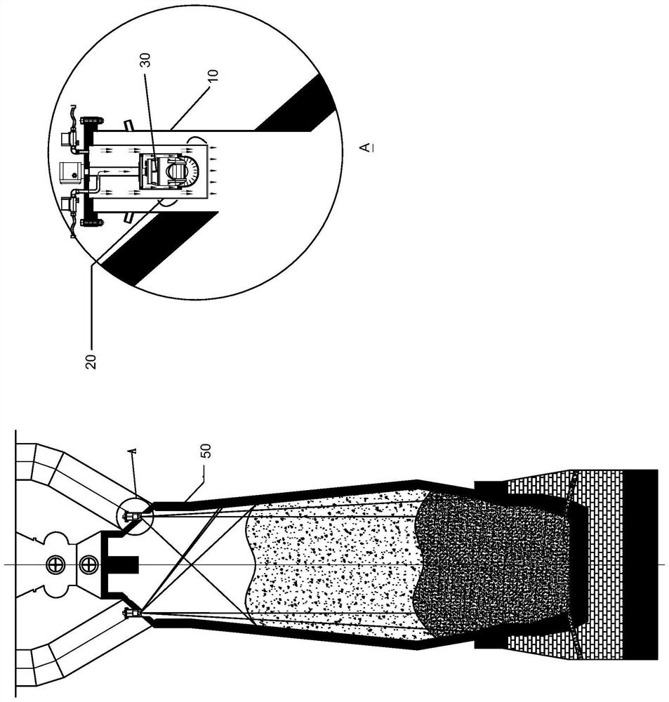
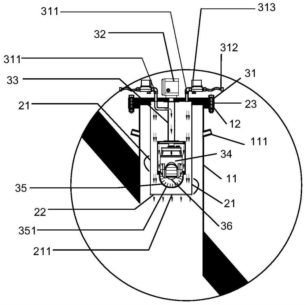
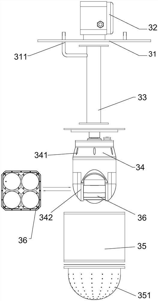
[0033] See attached figure 1 with 2 , figure 1 with 2 The main structure of a 3D radar scanner used for blast furnace charge level imaging is shown as an example, such as figure 1As shown, the 3D radar scanner 100 for blast furnace material surface imaging provided by the present invention may include: a base component 10 installed on the top of a blast furnace 50 , a high temperature isolation cover component 20 and a multi-dimensional radar component 30 . The base component 10 includes a base protection tube 11 and a base flange 12. One end of the base protection tube 11 communicates with the blast furnace 50, and the other end is fixedly connected to the base flange 12. The base protection tube 11 is provided with at least one first inlet Air port 111. The high-temperature isolation cover member 20 includes an isolation cover protective pipe 21 , a temperature insulation plate 22 and an isolation cover flange 23 . The isolation cover protection tube 21 is located in th...


PUM


Abstract

The present invention provides a 3D radar scanner for blast furnace charge level imaging and a blast furnace charge level detection system. The 3D radar scanner includes a base component installed on the top of the blast furnace, a high-temperature isolation cover component and a multi-dimensional radar component. The seat component includes the base protective tube and the base flange; the high temperature isolation cover component includes the isolation cover protective tube, the heat insulation plate and the isolation cover flange; the radar component includes the radar flange, the junction box, the boom, and the multi-dimensional manipulator and a radar ranging unit. The blast furnace charging level detection system includes: at least one 3D radar scanner as mentioned above and a host computer. The invention can continuously measure the shape of the material surface in the blast furnace, provides visual data basis for ironworkers to adjust the charging process of the blast furnace, and has high economic benefits.

Description

technical field [0001] The invention relates to the field of radar level scanners, in particular to a 3D radar scanner for blast furnace charge level imaging and a blast furnace charge level detection system. Background technique [0002] Blast furnace production is an important part of iron and steel smelting, and a good shape of the material surface inside the blast furnace is of great significance to improve production efficiency and reduce combustion ratio. However, the internal working environment of the blast furnace is extremely harsh: high temperature, high pressure, large dust, and high gas concentration inside contains adhesive tar, which brings great difficulties to the measurement of the material level. [0003] In order to control the uniform distribution of the charge level of the blast furnace, it is necessary to clearly understand the distribution state of the charge level in the blast furnace. At present, most of the detection methods for blast furnace mate...

Claims


Application Information

Patent Timeline
Patent Type & Authority Patents(China)
IPC IPC(8): G01S13/42G01S7/41G01F23/284C21B7/24
CPCC21B7/24G01F23/284G01S7/41G01S13/426G01S13/428
Inventor 孙丰凯
Owner BEIJING JINDE CHUANGYE CONTROL TECH
Why Eureka
Try Eureka