Integrated mechanical environment-friendly treatment equipment for industrial waste gas

A technology for environmental protection treatment and industrial waste gas, which is applied to the separation of dispersed particles, chemical instruments and methods, and filtration of dispersed particles. It can solve the problems of inconvenient replacement, difficult dust particles, and reduced waste gas treatment effect. The effect of complete removal

Active Publication Date: 2020-06-16
YANGZHOU LVQUAN ENVIRONMENTAL ENG TECH
View PDF23 Cites 1 Cited by
  • Summary
  • Abstract
  • Description
  • Claims
  • Application Information

AI Technical Summary

Problems solved by technology

[0005] 1. During the actual use of the device, the structure for filtering the dust particles in the exhaust gas cannot be easily replaced. After the dust particles block the filter structure, it will make it difficult for the device to filter the dust particles in the exhaust gas, reducing the pollution of the exhaust gas. the effect of the treatment;
[0006] 2. During the actual use of the device, the desulfurizer and denitrification agent cannot fully contact with the exhaust gas, and the mixture with the exhaust gas is not uniform enough, which makes it difficult for the desulfurizer and denitrification agent to fully exert their effectiveness and reduces the waste gas treatment. Effect;
[0007] 3. During the actual use of the device, the desulfurizer and denitrification agent will precipitate after long-term storage, which will easily reduce the use effect of the desulfurizer and denitrification agent

Method used


Image

  • Integrated mechanical environment-friendly treatment equipment for industrial waste gas
  • Integrated mechanical environment-friendly treatment equipment for industrial waste gas
  • Integrated mechanical environment-friendly treatment equipment for industrial waste gas

Examples


Embodiment Construction

[0035] In order to make the technical means, creative features, goals and effects achieved by the present invention easy to understand, the present invention will be further described below in conjunction with specific embodiments.

[0036] In describing the present invention, it is to be understood that the terms "center", "upper", "lower", "front", "rear", "left", "right", "vertical", "horizontal", The orientations or positional relationships indicated by "top", "bottom", "inner", "outer", etc. are based on the orientations or positional relationships shown in the drawings, and are only for the convenience of describing the present invention and simplifying the description, rather than indicating or implying the It should not be construed as limiting the invention that a device or element must have a particular orientation, be constructed, and operate in a particular orientation.

[0037]In the description of the present invention, it should be noted that, unless otherwise s...


PUM


Abstract

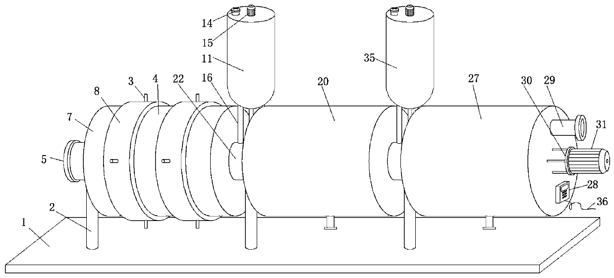
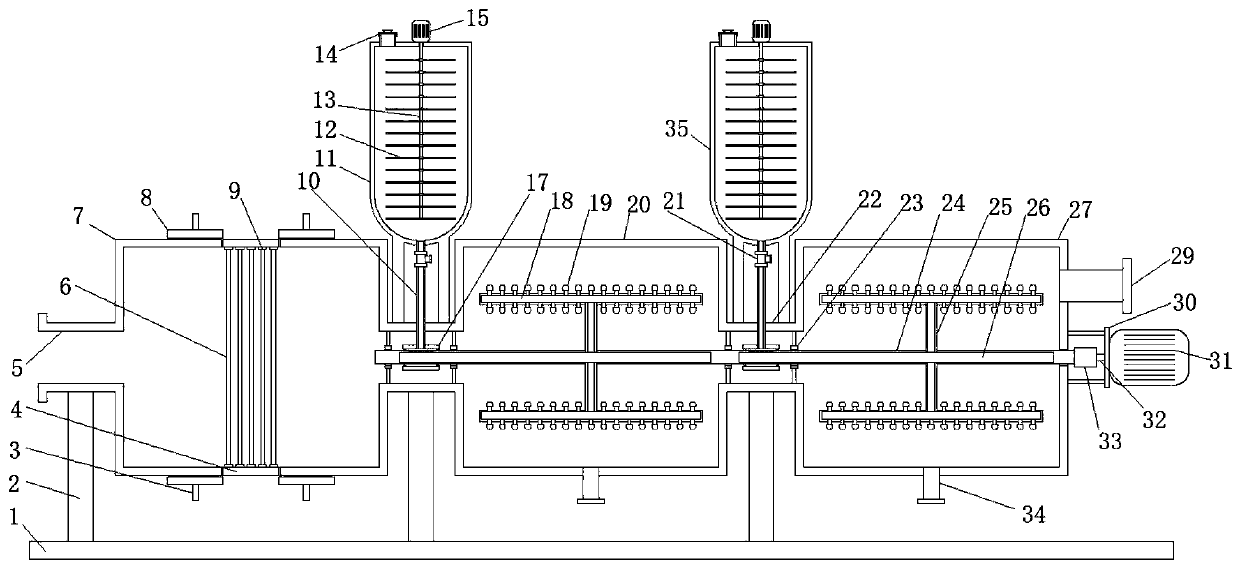
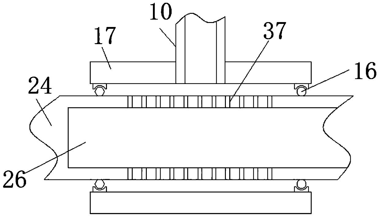
The invention relates to the technical field of waste gas treatment, and discloses integrated mechanical environment-friendly treatment equipment for industrial waste gas. The equipment comprises a support plate, a filter cartridge, a storage tank A, a storage tank B, a desulfurization cylinder, a denitration cylinder, a waste gas inlet pipe and a waste gas outlet pipe, wherein a fixed pipe is movably embedded in the middle of the filter cartridge, a fixed ring is in threaded connection with the inner wall of the fixed pipe, a filter gauze is fixedly bonded to the inner wall of the fixed ring,a connecting ring is in threaded connection with the outer wall of the filter cartridge, and a power assisting rod is fixedly welded to the outer wall of the connecting ring; and a PLC is fixedly installed at the bottom of the right side face of the denitration cylinder through bolts, a power line is connected to the bottom of the PLC, and an installation frame is fixedly welded to the middle ofthe right side face of the denitration cylinder. In the actual use process, a denitration agent and a desulfurizing agent can be atomized and sprayed into the waste gas, so that the desulfurizing agent and the denitration agent can be in full contact with the waste gas, and sulfide and nitride in the waste gas can be more thoroughly removed by the equipment.

Description

technical field [0001] The invention relates to the technical field of waste gas treatment, in particular to an integrated mechanical environmental protection treatment equipment for industrial waste gas. Background technique [0002] Industrial waste gas refers to the general term for all kinds of pollutant gases that are discharged into the air during fuel combustion and production processes in the factory area. These exhaust gases include: carbon dioxide, carbon disulfide, hydrogen sulfide, fluoride, nitrogen oxides, chlorine, hydrogen chloride, carbon monoxide, sulfuric acid (mist) lead mercury, beryllium compounds, smoke and productive dust, which will pollute the air when discharged into the atmosphere. These substances enter the human body through the respiratory tract in different ways, some directly cause harm, and some have a cumulative effect, which will seriously endanger human health. [0003] The invention with the Chinese patent number CN201810664723.X disclo...

Claims


Application Information

Patent Timeline
Patent Type & Authority Applications(China)
IPC IPC(8): B01D53/78B01D53/48B01D53/54B01D46/12
CPCB01D53/78B01D53/48B01D53/54B01D46/12
Inventor 吴国平
Owner YANGZHOU LVQUAN ENVIRONMENTAL ENG TECH
Why Eureka
Try Eureka