Double vertical clamping structure for finely adjusting double-worm-wheel fly cutter radially

A technology of double worm gears and flying knives, applied in the direction of worm gears, gear teeth, elements with teeth, etc., can solve the problems of reducing productivity, increasing cutting resistance, weakening the strength and rigidity of the tool bar, and achieving self-closing of positioning and clamping. Reliable, low rolling friction loss, flexible movement and anti-rust effect

Pending Publication Date: 2020-06-16
中钢集团衡阳机械有限公司
View PDF0 Cites 1 Cited by
  • Summary
  • Abstract
  • Description
  • Claims
  • Application Information

AI Technical Summary

Problems solved by technology

This kind of clamping structure has a large clamping force, and the flying knife is not easy to loosen. However, these two clamping structures are arranged along the radial direction of the knife bar to install the round tie rod and the round hole of the flying knife to cross vertically, which weakens the strength and rigidity of the knife bar. This vertical staggered hole structure is suitable for occasions where the diameter of the working worm (cutter bar) and the center distance between adjacent flying knives are relatively large, so the use of multiple flying knives is limited, and in order to avoid the difficulty of manufacturing and adjusting the flying knives of multiple flying knives , had to be replaced by a single flying knife, reducing productivity
Because the number of flying knives is very small and the cutting volume is large, the cutting edge is easy to wear, and the local wear increases quickly, which increases the cutting resistance, and because the flying knives are tangentially fed, when the flying knives roll from the cutting end to the cutting end At the end, the cutting edge of the flying knife cuts from one side to both sides and then to the other side, and the flying knife generates a large periodic alternating torque along its axis. There is a small gap in the round hole, and it is affected by the rigidity of the tool holder and the supporting end and the gap between the rotating parts such as the bearing. The poor dynamic stiffness will easily cause vibration, and the flying knife will loosen, fall off or even be broken under the action of alternating cutting impact force. Worm gears, etc.; especially the diameter of the working worm is small, the modulus or cutting force is large, especially the cutting conditions of the cutting edges on both sides of the flying knife with a large lead angle are quite different, and the above clamping structure is not competent

Method used


Image

  • Double vertical clamping structure for finely adjusting double-worm-wheel fly cutter radially
  • Double vertical clamping structure for finely adjusting double-worm-wheel fly cutter radially
  • Double vertical clamping structure for finely adjusting double-worm-wheel fly cutter radially

Examples


Embodiment approach 1

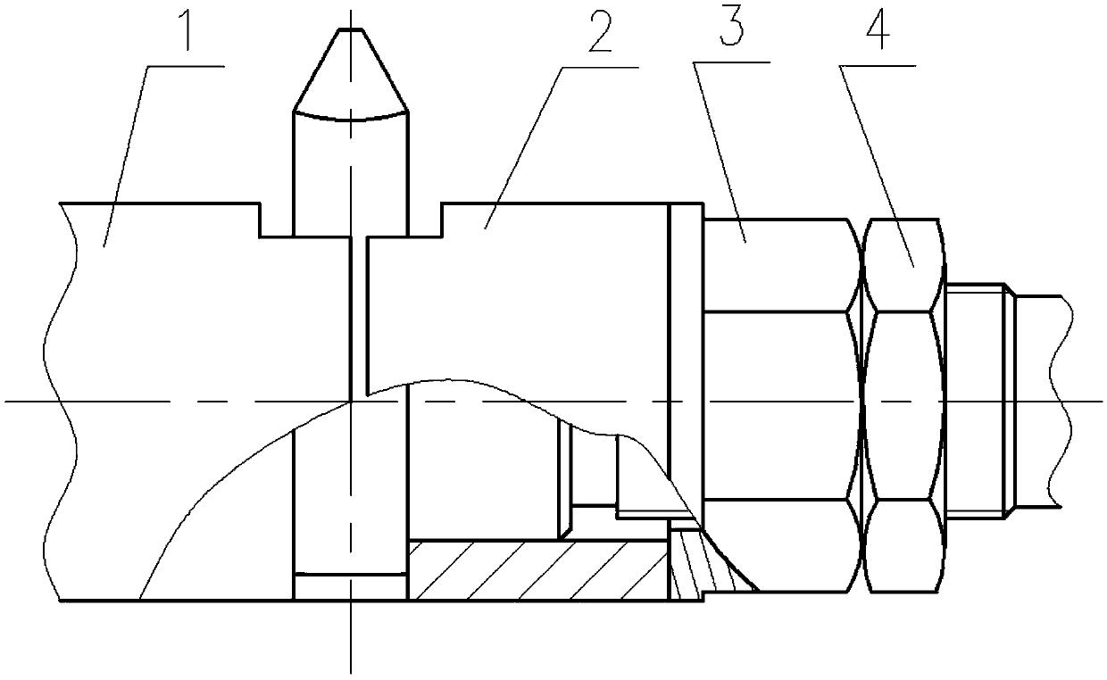
[0075] Such as Figure 4The shown clamping structure of a double worm gear flying knife includes a tool bar 1, which is composed of a driving end with a tapered shank (not shown in the figure) and a slender passive end. The passive end is provided with a central hole 4 facing the active end and concentric with the centerline of rotation of the tool bar 1, and a mounting and clamping device is provided radially along the center line of tool bar 1 rotation (in the axial direction) at a proper position in the middle of the tool bar 1. Tighten and fine-tune the two parallel, two-stage stepped concentric holes 2 of the large and small holes in the same direction of the straight handle 72 of the flying knife. The large holes of the two stages of the concentric holes 2 are cylindrical holes and the small holes are screw holes 22. The center distance between the two stages of stepped concentric holes 2 is the axial tooth pitch of a working worm πm, and the locking screw 8 is provided ...

Embodiment approach 2

[0125] Figure 5 Reflecting the specific structure of another embodiment of the present invention, this embodiment is different from Embodiment 1, mainly in that the force applying member 6 is an electro-hydraulic push rod or a hydraulic or pneumatic cylinder and a gas-hydraulic booster mechanism. Positioning and connection with the cutter bar 1; specifically, the larger diameter part of the central hole 4 (entry end) is a circular light hole 42, so as to facilitate the sliding positioning of the force applying member 6. On the passive end surface 11 There are several screw holes connected with the force applying member 6, and the hobbed worm wheel is left-handed.

[0126] A further technical solution is: the force-applying member 6 adopts an electro-hydraulic push rod or a hydraulic or pneumatic cylinder and a gas-hydraulic booster mechanism, and the axial force is generated by hydraulic, pneumatic or electric energy. The piston rod serves as a force application terminal 61,...

Embodiment approach 3

[0130] Image 6 Reflecting the specific structure of another embodiment of the present invention, this embodiment is different from Example 2 in that the force applying member 6, and δ=0°, specifically, the force applying member 6 adopts a spring or a spring assembly, Image 6 Shown in the central center hole 4 is the Belleville spring and adjusting flat washer.

[0131] A further technical solution is: the force applying mechanism member 6 adopts a spring or a spring assembly, and the spring is uniformly elastically deformed after being compressed by force, and the elastic force generates an axial force, which pushes the force applying terminal 61 to move axially, and adjusts the flat washer or screw Adjust the stretch.

[0132] When the spring is stressed and compressed, it deforms uniformly and elastically, and the force application terminal 61 moves axially to generate an axial force. Through several of the balls 9, the opposite ends of the first positioning push rod and ...


PUM


Abstract

The invention discloses a double vertical clamping structure for finely adjusting a double-worm-wheel fly cutter radially. A center hole which faces the active end and is concentric with a rotating central line of a cutter bar is formed in the passive end of the cutter bar, two parallel two-section stepped concentric holes for mounting, clamping and finely adjusting the fly cutter are radially formed along the rotating central line of the cutter bar, large holes of the two-section stepped concentric holes are cylindrical holes, small holes of the two-section stepped concentric holes are screwthrough holes, and the center distance between the two-section stepped concentric holes is the axial tooth pitch of a working worm; two sections of threads which are the same in screwing direction anddifferent in screw pitch are arranged on a locking screw and correspondingly connected with the screw through holes and a screw hole formed in a fly cutter round straight handle, so that the fly cutter is never loosened after being finely adjusted and clamped in the radial direction of the cutter bar; and a positioning clamping mechanism is arranged in the center hole, the oblique end faces of the opposite ends of a positioning jacking rod slide onto the obliquely-beveled plane of the fly cutter round straight handle to form close face contact under the combined action of the locking screw and a force applying component, and the fly cutter is fastened in the corresponding cylindrical hole and located at the correct position. The radial fine-adjusting and positioning double vertical clamping technical scheme is suitable for high-precision and large-cutting-force rolling cutting of multi-head worm wheels.

Description

technical field [0001] The invention relates to a double vertical clamping structure of a radial fine-tuning double worm gear flying knife, which is mainly used for hobbing of a multi-head worm gear driven by a cylindrical worm with a large lead angle and a large lead angle with small diameter, high precision and large cutting resistance. Background technique [0002] When hobbing and cutting worm gears, because the basic geometric parameters of the worm gear hob must generally be the same as the working worm (that is, the worm meshed with the worm gear to be hobbed), the worm gear hob is a highly targeted special tool with low utilization rate and high price. The production cycle is long and it is not economical to use, and it is difficult to manufacture multi-head worm gear hobs. It is not economical to manufacture worm gear hobs in single-piece small batch production. Toothed worm gear hob, its gear cutting principle is the same as that of tangential worm gear hob. The m...

Claims


Application Information

Patent Timeline
Patent Type & Authority Applications(China)
IPC IPC(8): B23F23/12B23F11/00
CPCB23F11/00B23F23/1243
Inventor 周湘衡
Owner 中钢集团衡阳机械有限公司
Why Eureka
Try Eureka