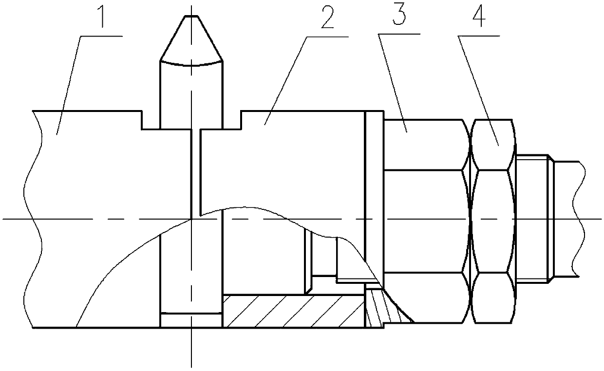
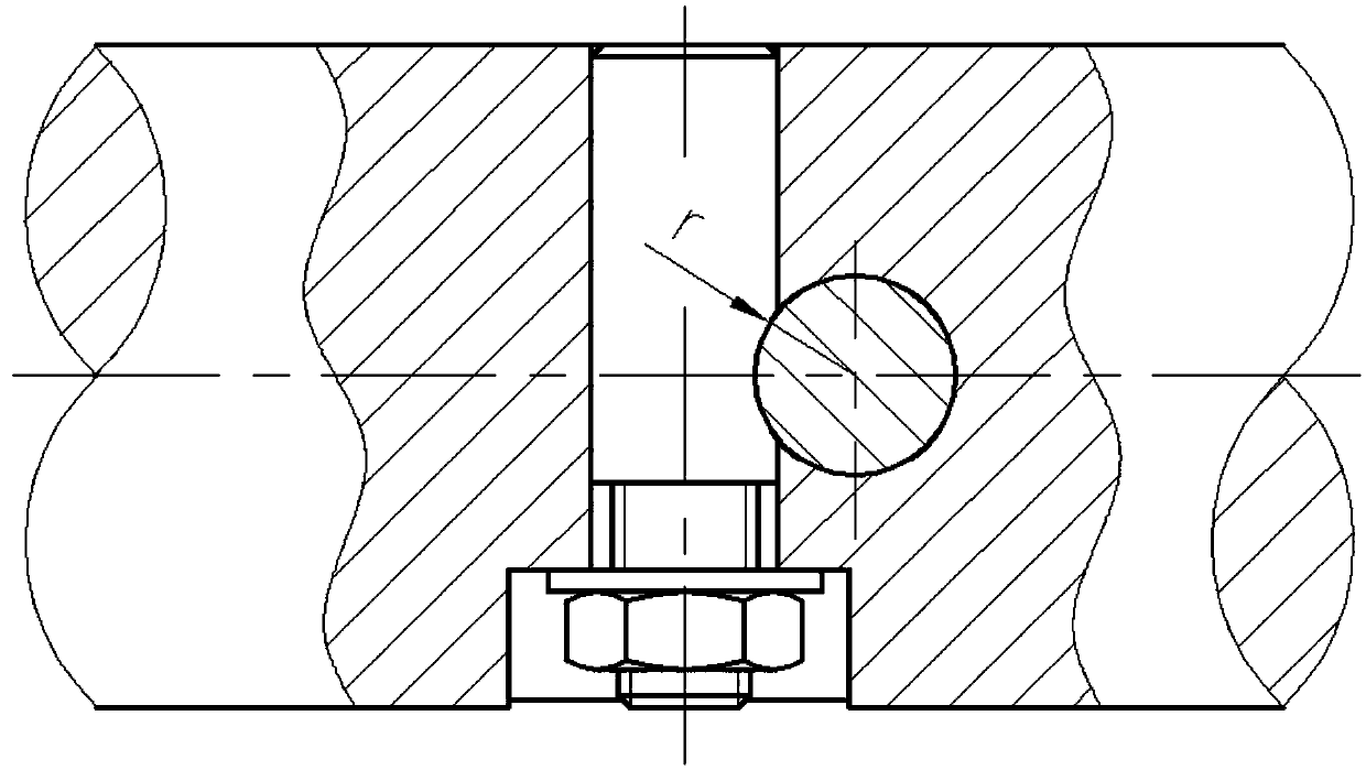
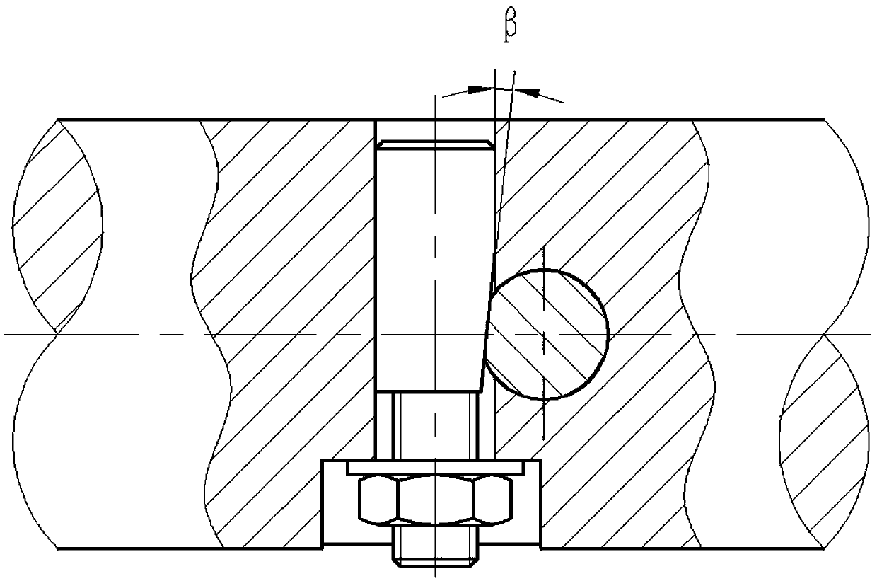
Double vertical clamping structure of dual-worm-gear fly knives
A technology of double worm gears and flying knives, applied in the direction of worm gears, gear teeth, components with teeth, etc., can solve the problems of difficult clamping structure, increase cutting resistance, reduce productivity, etc., and achieve reliable positioning, clamping, self-locking, rolling Less friction loss, flexible movement and anti-rust effects
- Summary
- Abstract
- Description
- Claims
- Application Information
AI Technical Summary
Problems solved by technology
Method used
Image
Examples
Embodiment approach 1
[0070] Such as Figure 4 The shown clamping structure of a double worm gear flying knife includes a tool bar 1, which is composed of a driving end with a tapered shank (not shown in the figure) and a slender passive end. The passive end is provided with a central hole 4 facing the active end and concentric with the centerline of rotation of the cutter bar 1, and a mounting and pulling mechanism is installed radially along the center line of rotation of the tool bar 1 (in the axial direction) at an appropriate position in the middle of the tool bar 1. Tighten the two parallel connection through holes 2 of the straight handle 72 of the flying knife. The center distance between the connection through holes 2 is the axial tooth pitch of a working worm. There is a plane 21, wherein the plane 21 on the same side of the center line of rotation of the cutter bar 1 is provided with a tension screw 10, and is connected with the screw hole provided on the axis line of the flying knife st...
Embodiment approach 2
[0119] Figure 5 Reflecting the specific structure of another embodiment of the present invention, this embodiment is different from Embodiment 1, mainly in that the force applying member 6 is an electro-hydraulic push rod or a hydraulic or pneumatic cylinder and a gas-hydraulic booster mechanism. Positioning and connection with the cutter bar 1; specifically, the larger diameter part of the central hole 4 (entry end) is a circular light hole 42, so as to facilitate the sliding positioning of the force applying member 6. On the passive end surface 11 There are several screw holes connected with the force applying member 6, and the hobbed worm wheel is left-handed.
[0120] A further technical solution is: the force-applying member 6 adopts an electro-hydraulic push rod or a hydraulic or pneumatic cylinder and a gas-hydraulic booster mechanism, and the axial force is generated by hydraulic, pneumatic or electric energy. The piston rod serves as a force application terminal 61,...
Embodiment approach 3
[0124] Image 6 Reflecting the specific structure of another embodiment of the present invention, this embodiment is different from Example 2 in that the force applying member 6, and δ=0°, specifically, the force applying member 6 adopts a spring or a spring assembly, Image 6 Shown within the central center hole 4 is the Belleville spring and adjusting flat washer.
[0125] A further technical solution is: the force application member 6 adopts a spring or a spring assembly, and the spring deforms uniformly and elastically after being compressed by force, and the elastic force generates an axial force, which pushes the force application terminal 61 to move axially, and is adjusted by adjusting a flat washer or a screw. elastic.
[0126]When the spring is stressed and compressed, it deforms uniformly and elastically, and the force terminal 61 moves axially to generate an axial force. Through several balls 12, the opposite ends of the first positioning push rod and the second p...
PUM
 Abstract
Description
Claims
Application Information
 - R&D
- Intellectual Property
- Life Sciences
- Materials
- Tech Scout
- Unparalleled Data Quality
- Higher Quality Content
- 60% Fewer Hallucinations
Browse by: Latest US Patents, China's latest patents, Technical Efficacy Thesaurus, Application Domain, Technology Topic, Popular Technical Reports.
© 2025 PatSnap. All rights reserved.Legal|Privacy policy|Modern Slavery Act Transparency Statement|Sitemap|About US| Contact US: help@patsnap.com


