
Micro-pore anode used for cluster plasma spray gun and cluster plasma spraying method

A plasma spray gun, plasma technology, applied in the direction of coating, molten spraying, metal material coating process, etc., can solve the problems of large plasma jet spots, reduced production efficiency, poor concentration of plasma jets, etc., to alleviate the overall decline in mechanical properties , Avoid evaporation and burning loss, the effect of energy density concentration

Pending Publication Date: 2020-06-16
TIANJIN UNIV
View PDF2 Cites 2 Cited by
  • Summary
  • Abstract
  • Description
  • Claims
  • Application Information

AI Technical Summary

Problems solved by technology

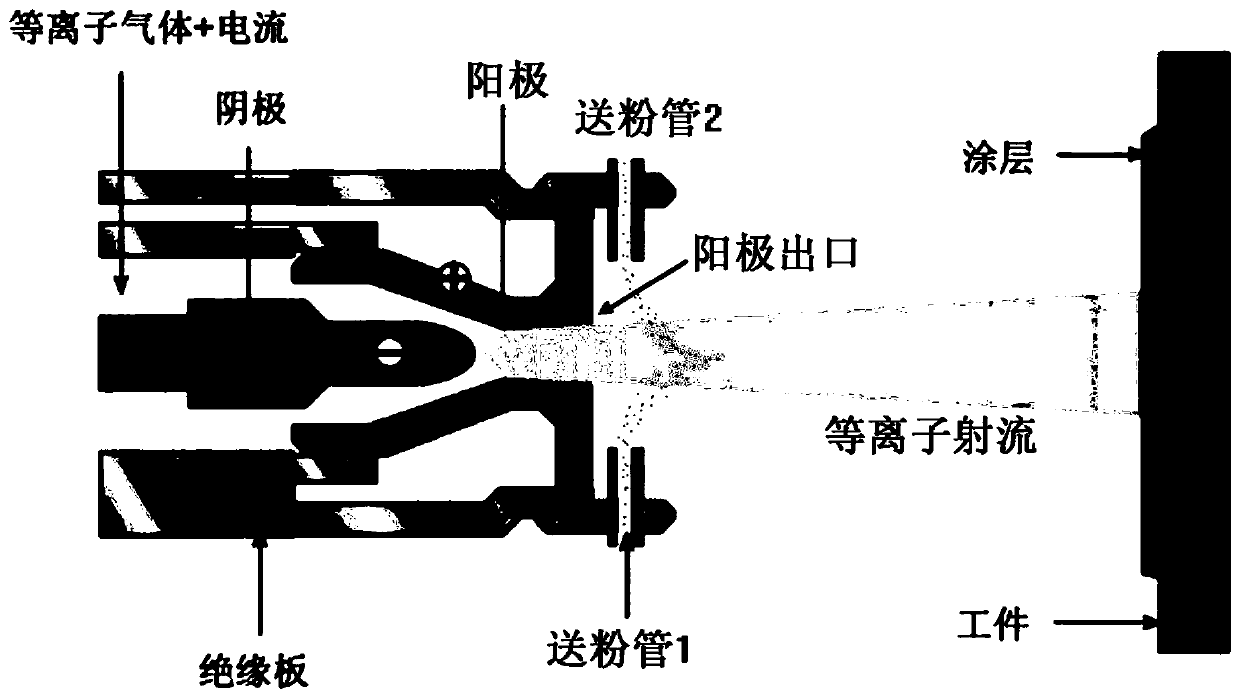
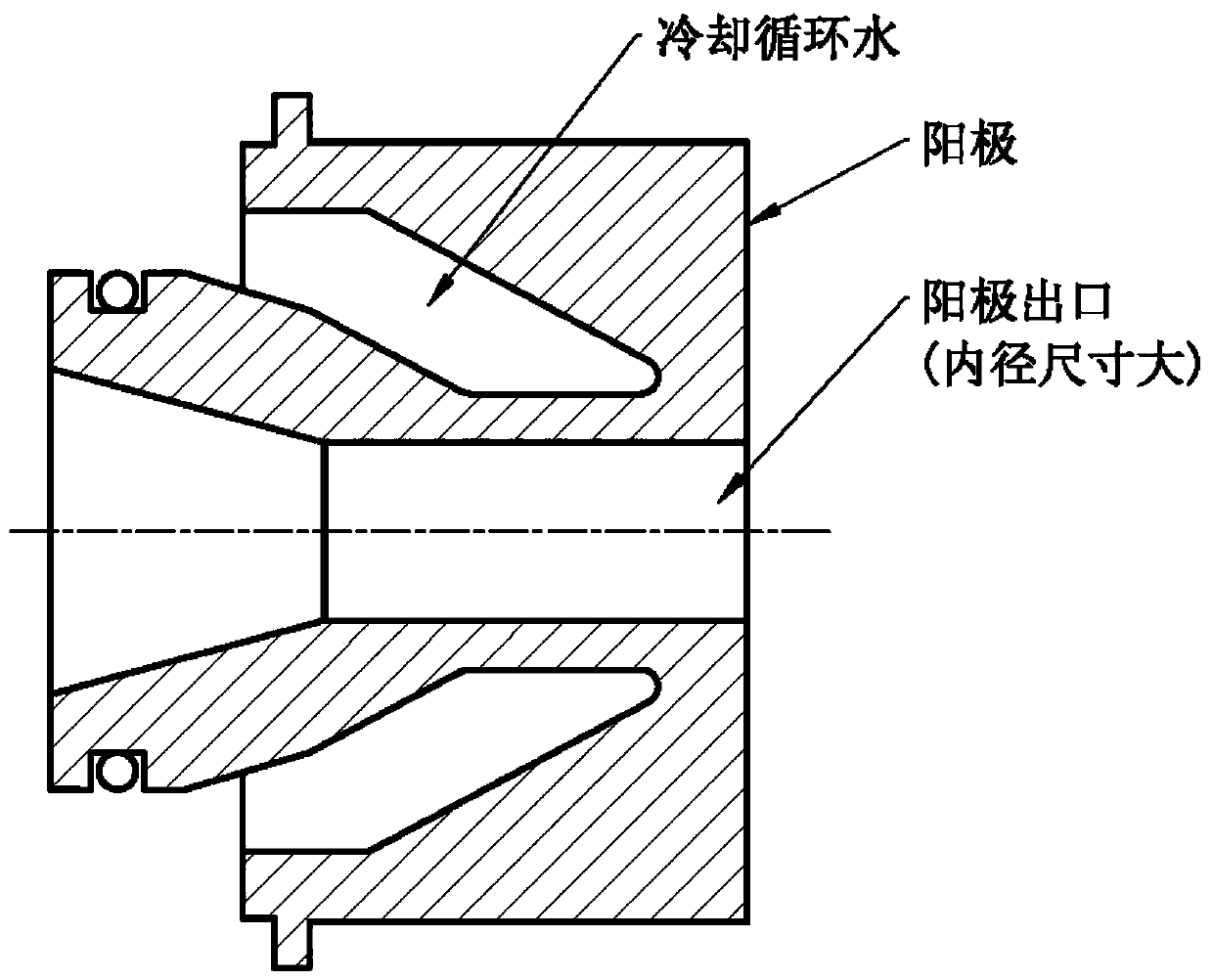
[0015] (2) Since the inner diameter of the anode outlet is usually 5-20 mm and the size is large, it will inevitably lead to large spots on the plasma jet
However, the farther the spraying distance is, the less concentrated the plasma jet is and the less dense the prepared coating is
[0016] (3) In the existing plasma spraying process, the temperature of the substrate is generally controlled below 300-400 degrees Celsius, and the surface of the substrate does not melt. The bonding method between the prepared coating and the substrate is mechanical bonding, and the bonding force is usually lower than 40MPa. Compared with metallurgical bonding, the bonding strength between the coating and the substrate is low, resulting in the coating being prone to partial peeling or even overall peeling during the service process of the coating, and the working life of the coating is short
[0017] (4) The concentration of the plasma jet of the existing plasma spraying is poor; the uniformity of the powder feeding of a single powder feeding pipe or two powder feeding pipes is also poor
As a result, the speed and temperature of the powder particles heated and accelerated by the plasma jet are different, and the uniformity is poor. The prepared coating is easy to contain unmelted powder particles, and the powder particles that are not deposited as a coating fly to the surrounding environment. , the deposition efficiency of powder materials is low
It not only pollutes the environment, but also increases the consumption of powder for preparing coatings per unit area, thereby reducing production efficiency and increasing production costs

Method used


Image

  • Micro-pore anode used for cluster plasma spray gun and cluster plasma spraying method
  • Micro-pore anode used for cluster plasma spray gun and cluster plasma spraying method
  • Micro-pore anode used for cluster plasma spray gun and cluster plasma spraying method

Examples


Embodiment Construction

[0045] The above and other objects, features and advantages of the present invention will be more apparent through the following description of the embodiments of the present invention with reference to the accompanying drawings. The present invention is described below based on the embodiments, and those skilled in the art should understand that the drawings provided here are for illustration purposes, and the drawings are not necessarily drawn to scale.

[0046] Unless the context clearly requires, throughout the specification and claims, "comprises", "comprises" and similar words should be interpreted in an inclusive sense rather than an exclusive or exhaustive meaning; that is, "including but not limited to" meaning.

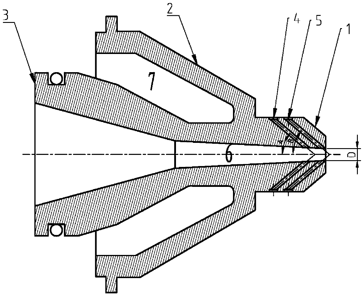
[0047] Such as image 3 with Figure 4 As shown, the invention discloses a microporous anode for a cluster plasma spray gun, which comprises an anode front part (1), an anode middle part (2) and an anode rear part (3), and is coaxially connected with the p...


PUM


Abstract

The invention provides a micro-pore anode used for a cluster plasma spray gun and a cluster plasma spraying method. The micro-pore anode comprises an anode front part, an anode middle part and an anode rear part, wherein the anode front part is designed with a powder conveying channel and a protective gas conveying channel; the inner diameter of an outlet of the micro-pore anode is limited withina range of 0.5-3 millimeters; micro-pore anode compression effect is utilized to obtain plasma micro jet flow which is focused in energy density and is small in divergence, and a local area on the surface of a to-be-sprayed workpiece is instantaneously molten while the integral temperature of the workpiece is prevented from rising, so that a coating and a basal body generate metallurgical bonding;the powder conveying channel which is in peripheral ring-shaped distribution is used for enabling powder to form tapered powder flow with a pre-designed included angle and small divergence, so that powder is heated and accelerated more uniformly in plasma micro jet flow to obtain a sprayed coating which is uniform in chemical component, is compact in micro structure, and defines metallurgical bonding.

Description

technical field [0001] The invention relates to the fields of plasma spraying, remanufacturing and repairing, in particular to a microporous anode for a cluster plasma spray gun and a cluster plasma spraying method. The compression effect obtains the plasma micro-jet with concentrated energy density and small divergence. The spots of the plasma micro-jet are small, which is suitable for surface coating processing of precision parts, tiny parts, and thin-walled parts. At the same time, the position of the jet heating workpiece can be concentrated In the small jet spot area, while avoiding the overall temperature rise of the workpiece, it instantly melts the local area of ​​the surface of the workpiece to be sprayed, so that the coating and the substrate are metallurgically bonded; the powder is formed by using the circumferentially distributed powder delivery channel with a pre-designed The conical powder flow with small angle and divergence makes its heating and acceleration m...

Claims


Application Information

Patent Timeline
IPC IPC(8): C23C4/134C23C4/06
CPCC23C4/134C23C4/06
Inventor 叶福兴
Owner TIANJIN UNIV
Learn More