Light intelligent water quality detection system and method

A water quality detection and intelligent technology, applied in the field of inspection and detection, can solve the problems of pollution diffusion, large manpower and material resources, complexity, etc., and achieve the effect of ensuring stability, simple structure and good performance

Pending Publication Date: 2020-06-16
HANGZHOU DIANZI UNIV
View PDF12 Cites 0 Cited by
  • Summary
  • Abstract
  • Description
  • Claims
  • Application Information

AI Technical Summary

Problems solved by technology

[0003] (1) The biggest disadvantage is that it requires a lot of human participation and cannot automatically detect a water area intelligently
Secondly, manual detection of water areas requires a lot of manpower and material resources, and the detection efficiency is not very high.
The water quality detection of a certain river area or lake is mostly point-type detection, that is, a target detection point is randomly selected for random detection. The method requires too much manpower, cost and time
Therefore, most of the time, it is a small-scale manual detection with few sampling points. It is difficult to find the pollution source in a timely and effective manner and take timely and effective control measures, and it is also impossible to accurately locate the pollution source;
[0004] (2) Although it has multi-functional properties, the cumbersome measurement methods, a large amount of data and complex operations require the participants to have more accurate and correct operating procedures to obtain more accurate measurement data
These modules are not well integrated, which leads to the cumbersome and complicated use of testing instruments;
[0005] (3) It is impossible to form a complete and efficient system, that is, a system that includes intelligent detection, data upload, analysis, and positioning of polluted areas, etc., and provides timely feedback after detection
When the waters are polluted by humans or nature, it cannot be detected early and effectively treated, leading to further spread and aggravation of pollution

Method used


Image

  • Light intelligent water quality detection system and method
  • Light intelligent water quality detection system and method
  • Light intelligent water quality detection system and method

Examples


Embodiment 1

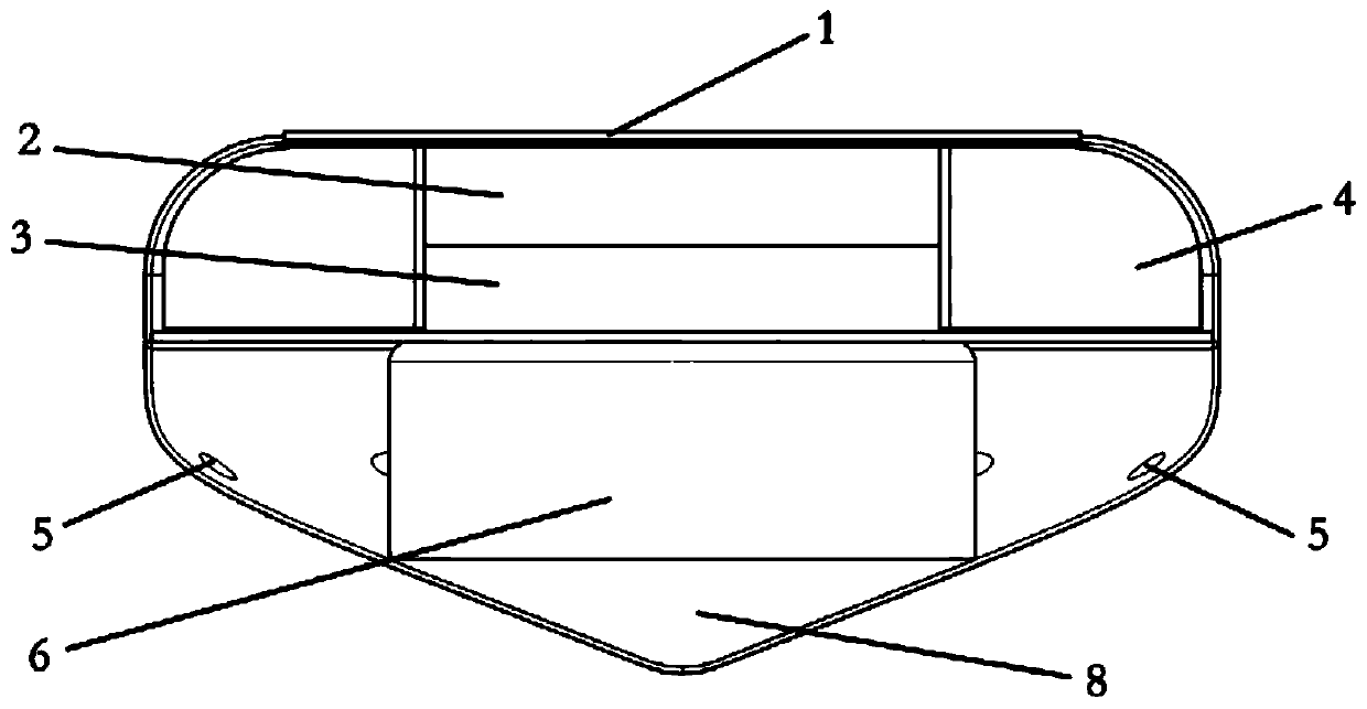
[0040] see figure 1 , 2, which is a schematic structural diagram of a lightweight intelligent water quality detection system according to an embodiment of the present invention, including a solar photovoltaic panel 1, a power module 2, a control communication positioning module 3, a buoyancy member 4, a detection unit 6, a counterweight 8 and a casing, in,

[0041] The solar photovoltaic electric panel 1 is arranged on the upper surface to charge the power module 2, and the power module 2 supplies power for the control communication positioning module 3 and the detection part 6; The detection part 6 and the counterweight 8 are arranged below the buoyancy part 4 and wrapped by the shell; the detection part 6 includes a temperature detection circuit, a pH detection circuit, a turbidity detection circuit, a conductivity detection circuit and a dissolved oxygen detection circuit .

[0042] Through the above settings, the upper part is a cylinder with a height of 75mm and a roun...

Embodiment 2

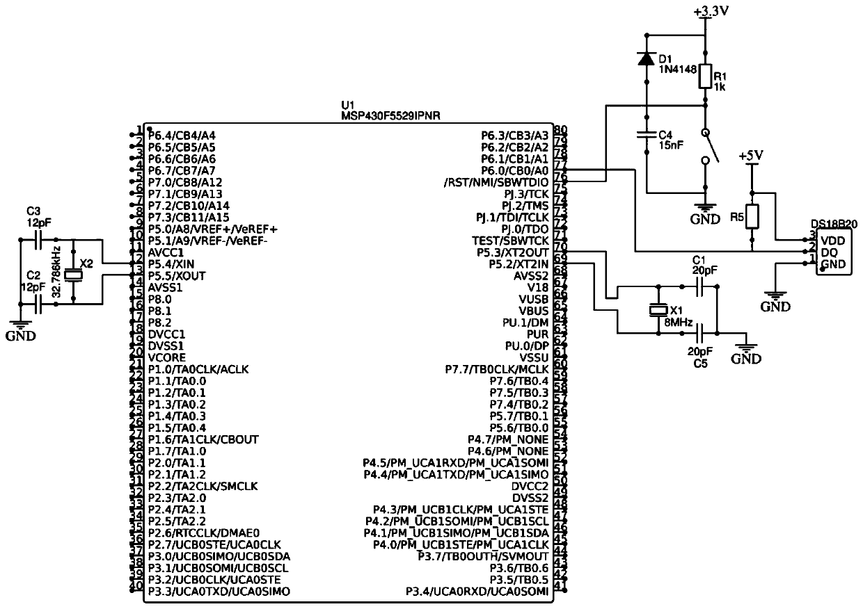
[0044] see image 3 It is the schematic diagram of temperature detection circuit, including temperature sensor DS18B20, and the control communication positioning module includes MSP430 chip. The temperature sensor DS18B20 uses an I / O port to communicate with the microprocessor MSP430 chip in two directions. The power supply is 3V-5.5V, and the measurement results are serially transmitted in 9-12 digits without any external components.

Embodiment 3

[0046] see Figure 4 , is the schematic diagram of the pH detection circuit, including pH electrode P1, TL431 chip U1, AD8663 chip U3 and two LM358 chips U2.1 / U2.2, wherein the pH electrode P1 generates a corresponding DC voltage change according to the pH change in the water, To convert the PH value signal into an electrical signal, the built-in ADC in the MSP430 chip collects a positive voltage of 0-2.5V, and the output voltage of the PH electrode P1 includes negative voltage. It is necessary to add a reference voltage to the PH electrode P1 as a bias, so that the output voltage is all Positive voltage, use TL431 chip U1, short its pin 1 and pin 2, get a stable output voltage on pin 1, and then divide the voltage through the sliding rheostat R2, and transmit the generated reference voltage to an LM358 chip U2 On the pin 3 of .1, connect its pin 1 and pin 2 to form a voltage follower, which is used for impedance isolation of the input terminal of the PH electrode P1 to ensure...


PUM

PropertyMeasurementUnit
thicknessaaaaaaaaaa
diameteraaaaaaaaaa

Abstract

The invention discloses a light intelligent water quality detection system and a light intelligent water quality detection method. The light intelligent water quality detection system comprises a solar photovoltaic panel, a power supply module, a control communication positioning module, a buoyancy piece, a detection part, a counterweight piece and an outer shell, wherein the solar photovoltaic panel is arranged on the upper surface and charges the power supply module, and the power supply module supplies power to the control communication positioning module and the detection part; the buoyancy piece is annularly arranged at the peripheries of the power supply module and the control communication positioning module; the detection part and the counterweight piece are arranged below the buoyancy piece and are wrapped by the outer shell; and the detection part comprises a temperature detection circuit, a PH detection circuit, a turbidity detection circuit, a conductivity detection circuitand a dissolved oxygen detection circuit. According to the light intelligent water quality detection system and the light intelligent water quality detection method, complete detection including intelligent detection, data uploading, analysis, polluted area positioning and the like is conducted and feedback is timely carried out, thus the problems that the pollution cannot be discovered as soon as possible and cannot be effectively treated and further diffusion and aggravation of the pollution are caused when a water area is polluted by human or nature are solved.

Description

technical field [0001] The invention belongs to the field of inspection and detection, and relates to a light-duty intelligent water quality detection system and method. Background technique [0002] The existing water pollution detection device is an environmentally friendly water quality detector that completes the detection of five basic water quality parameters: temperature, pH value, dissolved oxygen content, turbidity and conductivity. The detection process requires manual carrying of the device to the target detection area, use the collection device, and detect the collected water samples and collect data. When it is necessary to detect a certain range of river areas in a flowing manner, the device needs to be brought manually Go to ships and other water vehicles for testing. There are following deficiencies: [0003] (1) The biggest disadvantage is that it requires a lot of human participation, and it cannot automatically detect a water area intelligently. Secondl...

Claims


Application Information

Patent Timeline
Patent Type & Authority Applications(China)
IPC IPC(8): G01N27/30G01N27/409G01K7/00G01S19/42G01S19/13H02J7/35G05B19/042
CPCG01N27/302G01N27/409G01K7/00G01S19/42G01S19/13H02J7/35G05B19/0423Y02E10/56
Inventor 尹俊辉袁友伟周巧红余蕾俞子萱彭宇燃鄢腊梅
Owner HANGZHOU DIANZI UNIV
Why Eureka
Try Eureka