Infrared Band Cut Filter and Its Application

A cut-off filter, infrared band technology, applied in the field of optical film, can solve problems such as imaging distortion

Active Publication Date: 2022-04-15
ZHANGJIAGANG KANGDE XIN OPTRONICS MATERIAL
View PDF5 Cites 0 Cited by
  • Summary
  • Abstract
  • Description
  • Claims
  • Application Information

AI Technical Summary

Problems solved by technology

[0005] The main purpose of the present invention is to provide an infrared band cut-off filter and its application, to solve the imaging distortion caused by the RGB color ratio change caused by the half-wave hole in the infrared cut-off filter in the prior art under large-angle incidence The problem

Method used


Image

  • Infrared Band Cut Filter and Its Application
  • Infrared Band Cut Filter and Its Application
  • Infrared Band Cut Filter and Its Application

Examples


Embodiment 1

[0049] Simulation experiment data:

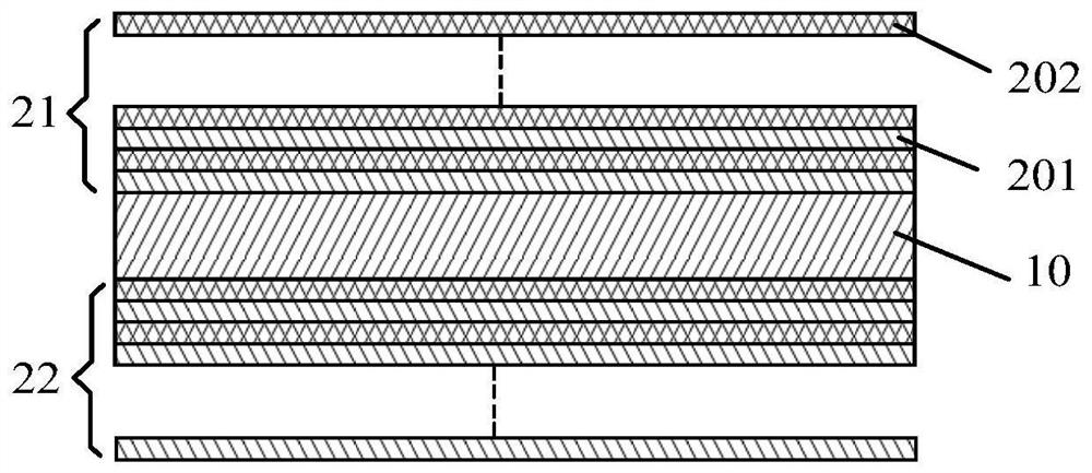
[0050] Infrared band cut filter structure such as figure 1 As shown, the first near-infrared reflective film 21, the transparent substrate layer 10, and the second near-infrared reflective film 22 are sequentially stacked, and the high-refractive-index material layer 201 forming a dual unit is a titanium dioxide layer with a refractive index of 2.354, and the low-refractive The refractive index material layer 202 is a silicon dioxide layer with a refractive index of 1.46. top-down:

[0051] The first film stack A in the first near-infrared reflective film 21 θ1 The monitoring wavelength is….nm, the center wavelength is….nm, V θ1 is..., which represents the adjustment factor of the optical thickness of the dual unit in the corresponding film stack relative to the preset monitoring wavelength. H1.808L 1.777H 1.806L 1.781H 1.794L 1.787H 1.802L 1.777H 1.805L 1.789H 1.799L1.786H 1.818L 1.783H 1.824L 1.802H 1.845L 1.815H 1.892L 1.892H 1.975L ...


PUM

PropertyMeasurementUnit
thicknessaaaaaaaaaa
refractive indexaaaaaaaaaa

Abstract

The invention provides an infrared band cut-off filter and its application. The infrared band cut-off filter sets the film structure in the reflective film system as │(α 1 Hβ 1 Lα 2 Hβ 2 L...α n Hβ n L)│ film stack, because the optical thickness coefficients (ie α, β) of the high refractive index material layer and the low refractive index material layer of the film stack follow the law of cosine waveform, that is, between adjacent high refractive index layers The distance between the distance and the distance between adjacent low-refractive index material layers presents a regular gradation of the cosine waveform, which will enhance the interference effect of wavelengths with smaller frequencies (such as near-infrared wavelengths). Using the above-mentioned interference effect and setting V θ To adjust the optical thickness of each film layer in the infrared band cut-off filter, the optical thickness difference of the film layers in the film stack can be made smaller, and the local decrease in the transmittance in the visible wavelength region is reduced when the incidence is large. probability.

Description

technical field [0001] The invention relates to the field of optical films, in particular to an infrared band cut-off filter and its application. Background technique [0002] With the widespread popularization of electronic products with camera functions such as smartphones, people's functional requirements for electronic products and camera performance requirements continue to increase, and the trend of thinner and lighter electronic products develops. The design requirements for the camera module are constantly improving, which means that the camera module must be able to withstand a larger incident light angle (>30°) to ensure the clarity and high degree of reproduction of the camera. [0003] In the camera module, an infrared cut-off filter is placed in front of the imaging detector CCD or CMOS, and its function is to pass through visible light and cut off infrared light. As the imaging pixels become higher and higher, CCD and CMOS have higher and higher requirement...

Claims


Application Information

Patent Timeline
Patent Type & Authority Patents(China)
IPC IPC(8): G02B5/20G02B5/26
CPCG02B5/201G02B5/208G02B5/26
Inventor 于甄孔德兴严振兴
Owner ZHANGJIAGANG KANGDE XIN OPTRONICS MATERIAL
Why Eureka
Try Eureka