Narrowband reflective film

A reflective film, narrow-band technology, applied in the field of narrow-band reflective film, can solve the problem of large reflection bandwidth of reflective film

Active Publication Date: 2019-04-09
ZHANGJIAGANG KANGDE XIN OPTRONICS MATERIAL
View PDF8 Cites 0 Cited by
  • Summary
  • Abstract
  • Description
  • Claims
  • Application Information

AI Technical Summary

Problems solved by technology

[0004] The main purpose of the present invention is to provide a narrow-band reflective film to solve the problem that the reflection bandwidth of the reflective film in the prior art is relatively large

Method used


Image

  • Narrowband reflective film
  • Narrowband reflective film
  • Narrowband reflective film

Examples


Embodiment 1

[0077] Simulation experiment data:

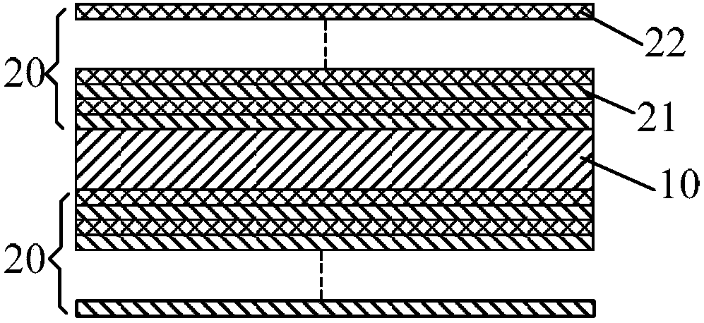
[0078] On the PET layer with a thickness of 0.05mm, an anti-reflection layer and a reflective film system (a layer of high refractive index material and a layer of low refractive index material are cross-stacked), wherein the center wavelength of the incident light is set to 532nm, and the high refractive index The index material layer is a titanium dioxide layer with a refractive index of 2.354, and the low refractive index material layer is a silicon dioxide layer with a refractive index of 1.46, wherein the antireflection layer is composed of a titanium dioxide layer and a silicon dioxide layer with an optical thickness of λ / 4, The optical thickness coefficient of the reflective film system is designed as:

[0079] 第一半膜堆:0.216H 1.836L 0.303H 1.691L 0.377H 1.591L 0.561H 1.501L0.583H 1.422L 0.677H 1.358L 0.762H 1.259L 0.851H 1.192L 0.928H 1.102L 1.010H1.020L 1.106H 0.921L 1.184H 0.886L 1.255H 0.767L 1.346H 0.714L 1.444H 0.634L1.552H 0.564...

Embodiment 2

[0084] The two half-film stacks of the narrow-band reflective film corresponding to Example 1 were fabricated by using the magnetron sputtering process, and the substrate (with a 0.05mm PET layer on the substrate) was cleaned with a clean cloth and ethanol. After degassing the vacuum chamber, use a vacuum cleaner to clean the inside of the bell jar, fill the molybdenum boat with the film material to be evaporated, and record the name of the film material of each boat. And place the substrate on the substrate frame, do not tilt the substrate. Drop the bell jar and evacuate the vacuum chamber according to the operation rules of the coating machine. When the vacuum reaches 7×10 -3 After Pa, pre-melt the film material in the molybdenum boat in turn to remove the gas in the film material. At this time, pay attention to block the film material with a baffle to ensure that the substrate will not be plated during pre-melting. When the vacuum degree reaches the requirement, the meth...

Embodiment 3

[0087] Simulation experiment data:

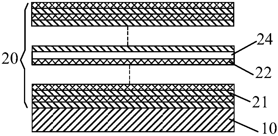
[0088] The optical thickness coefficient of the high-refractive index material layer and the optical thickness coefficient of the low-refractive index material layer of the film system are the same as in Example 1, and the two half-film stacks are arranged on two opposite surfaces of the PET layer. The light reflection performance of the above-mentioned narrow-band reflective film was simulated by using the Macleod film system design software, and the simulation results are shown in Figure 7 and Table 1.


PUM


Abstract

The invention provides a narrowband reflective film, which comprises a transparent substrate layer and a reflective film system. The reflective film system comprises n high/low refractive index material units and at least one film stack having a film system structure of |(alpha1H[beta]1L[alpha]2H[beta]2L...[alpha]mH[beta]mL)|, wherein, the H represents a high refractive index material layer, L represents a low refractive index material layer, and n and m are positive integers, wherein the 3<n<=150, 3<m<=50, m<=n. Alpha1, alpha2,..., and [alpha]m, and [beta]m,..., beta2, and beta1 of the same film stack independently satisfy the same gradient law on the same cosine waveform or sinusoidal waveform. For the i-th high/low refractive index material unit [alpha]iH[beta]iL, 1<=i<=n, [alpha]i represents the optical thickness of the i-th high refractive index material layer as a multiple of lambda/4, and [beta]i represents the optical thickness of the i-th low refractive index material layer asa multiple of lambda/4. The reflective film system or the transparent substrate layer is further provided with a light absorbing agent.

Description

technical field [0001] The invention relates to the field of optical film structures, in particular to a narrow-band reflective film. Background technique [0002] The existing reflective film is coated on the A side of the polymer PET substrate, and the B side is coated with metal aluminum. Among them, the A side is coated with HUD phosphor, dyeing material, nanosphere resin coating, etc., and the HUD phosphor, The bandwidth of the dyeing material and nanosphere resin is relatively wide, resulting in poor color gamut, serious whitening, and poor effect of the role of the optical device using the reflective film. At the same time, most of the reflective films on the market are full-band cut-off reflective films that use metal layers for reflection. Full-wavelength reflections cause the product to have extremely low transmittance and are basically opaque. However, some partial wavelength cut-off reflective films, because of their wide range of reflection wavelengths, cause a...

Claims


Application Information

Patent Timeline
Patent Type & Authority Applications(China)
IPC IPC(8): G02B5/08
CPCG02B5/085
Inventor 于甄张国臻夏振
Owner ZHANGJIAGANG KANGDE XIN OPTRONICS MATERIAL
Why Eureka
Try Eureka