
Low-temperature flue gas section free radical enhanced selective catalytic reduction denitration method and device

A low-temperature flue gas and free radical technology, applied in the field of flue gas denitrification, can solve problems such as increased production costs, difficult application of denitrification technology in power plants, and difficulty in obtaining temperature windows

Pending Publication Date: 2020-06-19
ZHENGZHOU UNIV
View PDF7 Cites 0 Cited by
  • Summary
  • Abstract
  • Description
  • Claims
  • Application Information

AI Technical Summary

Problems solved by technology

However, unlike power plant boilers, the flue gas temperature of industrial boilers and industrial kilns is usually low, which makes it difficult to obtain a suitable temperature window at the back end of the industrial kiln (ie, the low-temperature flue gas section)
Taking a small heating boiler as an example, after the exhaust gas passes through the multi-stage heat exchange equipment, the exhaust gas temperature is usually lower than 200°C, which makes it difficult to obtain a suitable temperature window at the rear end of the industrial furnace
Therefore, due to flue gas conditions, site area and cost constraints, mature power plant denitrification technology is difficult to be applied to industrial boilers and industrial kilns
To reach the temperature window, the back-end flue gas must be heated by an external heating device to increase its temperature, resulting in a significant increase in production costs

Method used


Image

  • Low-temperature flue gas section free radical enhanced selective catalytic reduction denitration method and device

Examples


Embodiment Construction

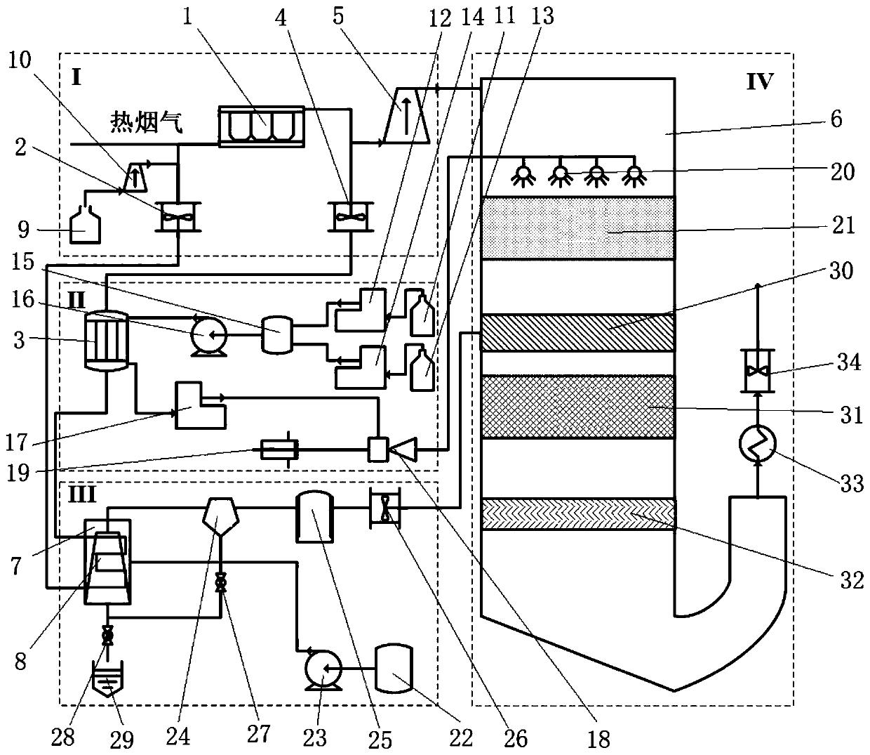
[0023] An embodiment of the free radical-enhanced selective catalytic reduction method in the low-temperature flue gas section of the present invention comprises the following steps:

[0024] 1) Extract part of the flue gas before the dust removal device into the preheating system, and the flue gas discharged from the preheating system and the flue gas after passing through the dust removal device enter the denitrification reactor together;

[0025] 2) Use the heat of the preheating system to preheat the hydrogen peroxide solution. The preheated hydrogen peroxide solution enters the denitration reactor and evaporates into hydrogen peroxide vapor at the temperature of the flue gas. Under the action of the first catalyst, the flue gas Oxidation treatment of NO in

[0026] 3) Using the heat of the preheating system to preheat the aqueous ammonia solution, so that the ammonia water turns into ammonia gas and enters the denitration reactor to mix with the oxidized flue gas in step ...


PUM


Abstract

The invention relates to a low-temperature flue gas section free radical enhanced selective catalytic reduction method and device. The device comprises a preheating system, a hydrogen peroxide preparation system, an ammonia gas preparation system and a denitration reactor. The method comprises firstly, extracting a part of flue gas in front of a dust removal device, feeding the flue gas into a preheating system, feeding the flue gas exhausted from the preheating system and the flue gas passing through the dust removal device into the denitration reactor together, preheating a hydrogen peroxidesolution by utilizing heat of the preheating system, enabling the preheated hydrogen peroxide solution to enter the denitration reactor, evaporating the preheated hydrogen peroxide solution into hydrogen peroxide steam at the temperature of the flue gas, oxidizing NO in the flue gas under the action of a first catalyst, preheating an ammonia water solution by utilizing the heat of the preheatingsystem, so that the ammonia water is changed into ammonia gas to enter the denitration reactor, and performing a denitration reaction process under the action of a second catalyst. Hydrogen peroxide oxidizes NO on the surface of the first catalyst, so that the reaction efficiency of reducing NO by NH3 under a low-temperature condition can be effectively improved, and denitration of low-temperatureflue gas sections of an industrial boiler and an industrial kiln is realized.

Description

technical field [0001] The invention relates to the field of flue gas denitrification, in particular to a free radical-enhanced selective catalytic reduction method and device in a low-temperature flue gas section. Background technique [0002] Industrial boilers and industrial kilns provide energy and heat sources for industrial production and national life. When air is used as the oxidant, nitrogen oxides are formed during thermochemical reactions. Excessive nitrogen oxides (NOx) in the air will form fine particles such as nitrate, which will seriously damage the heart and lung function of the human body and cause respiratory diseases; harm. If the glass furnace flue gas is directly discharged into the atmosphere without treatment, it will pose a serious threat to the ecological environment of our country. [0003] Mature power plant denitrification technologies are mainly non-selective catalytic reduction (SNCR) and selective catalytic reduction (SCR). These two matur...

Claims


Application Information

Patent Timeline
IPC IPC(8): B01D53/86B01D53/56
CPCB01D53/8631B01D2251/106B01D2251/2062B01D2258/0283
Inventor 韩一帆吴波
Owner ZHENGZHOU UNIV
Learn More