Supercharge Your Innovation With Domain-Expert AI Agents!

Overturning and positioning device for multiple silicon wafers

A technology for positioning devices and silicon wafers, which is applied in transportation and packaging, lighting and heating equipment, furnace components, etc., can solve the problems of low cell transport efficiency, achieve effective docking, and improve work efficiency

Pending Publication Date: 2020-06-19
SUZHOU MAXWELL TECH CO LTD
View PDF0 Cites 2 Cited by
  • Summary
  • Abstract
  • Description
  • Claims
  • Application Information

AI Technical Summary

Problems solved by technology

[0006] The invention overcomes the disadvantages of the prior art that the number of silicon wafers is turned over is limited, resulting in low cell transport efficiency, and provides a multi-silicon chip flipping positioning device. It is placed on the cell flipping mechanism, which flips multiple groups of cells synchronously and then makes them fall into the shuttle board positioning transmission mechanism, and the shuttle board positioning transmission mechanism transports multiple groups of cells to the next working station at the same time. Bit processing, improve work efficiency

Method used


Image

  • Overturning and positioning device for multiple silicon wafers
  • Overturning and positioning device for multiple silicon wafers
  • Overturning and positioning device for multiple silicon wafers

Examples


Embodiment 1

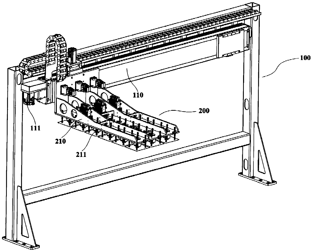
[0039] Combine figure 1 with image 3 , The multi-silicon wafer turning and positioning device of this embodiment includes a bracket 100, a suction cup lateral movement mechanism 200, and a shuttle board positioning and transmission mechanism 400. The bracket 100 is provided with a first sliding module 110 and a cell carrying mechanism 500. A sliding module 110 is used to drive the chuck transversal mechanism 200 to slide back and forth to the battery slice carrying mechanism 500 to grab the battery slices. The bottom of the suction cup traverse mechanism 200 is provided with a battery slice turning mechanism 300 for receiving battery slices. The turning mechanism 300 synchronously turns the received battery pack and makes it fall onto the shuttle positioning and transmission mechanism 400 for transportation.

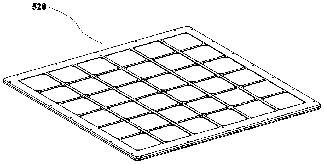
[0040] In this embodiment, the cell carrying mechanism 500 includes a carrier transport track 510 and a carrier 520 provided on the carrier transport track 510. The carrier...

Embodiment 2

[0047] The structure of a multi-silicon turning positioning device of this embodiment is basically the same as that of Embodiment 1. Further, the shuttle board positioning and transmission mechanism 400 in this embodiment includes a shuttle board lifting mechanism 410 and a driving shuttle board lifting mechanism 410 When the second sliding module 420 slides toward the battery piece turning mechanism 300, when the shuttle board lifting mechanism 410 slides to the bottom of the battery piece turning mechanism 300, the second vacuum suction cup 315 fails to vacuum to release the battery pieces.

[0048] Specifically, in this embodiment, the second sliding module 420 is driven by the second motor 422 provided on the shuttle board positioning transmission mechanism 400, and the second sliding module 420 drives the shuttle board lifting mechanism 410 to slide in the same direction as the first sliding mold. The sliding direction of the group 110 driving the suction cup traverse mechani...

Embodiment 3

[0051] The structure of a multi-silicon turning positioning device of this embodiment is basically the same as that of the second embodiment. Further, the positioning pin 412 in this embodiment is driven up and down by the cylinder 413 provided at the bottom of the shuttle board lifting mechanism 410. When the chip is placed on the silicon chip support plate 415, the air cylinder 413 retracts and the battery chip enters the positioning groove formed by the positioning pins 412.

[0052] In this embodiment, the silicon wafer support plate 415 is also provided with a graphite backing plate 414 for placing the battery pieces. The graphite backing plate 414 is arranged in an array on the silicon wafer support plate 415. Preferably, the graphite backing plate 414 is provided corresponding to each battery piece. , The graphite backing plate 414 can prevent the battery sheet from contacting other material parts to produce dirt, and play a role of isolation and protection for the battery ...


PUM


Abstract

The invention discloses an overturning and positioning device for multiple silicon wafers, and belongs to the technical field of solar cells. The overturning and positioning device comprises a supportand a shuttle plate positioning and conveying mechanism, wherein a first sliding module and a cell sheet bearing mechanism are arranged on the support, and the first sliding module is used for driving a sucker transverse moving mechanism to slide back and forth towards the cell sheet bearing mechanism so as to grab cell sheets; and a cell sheet overturning mechanism for receiving cell sheet setsis arranged at the bottom of the sucker transverse moving mechanism, and the cell sheet overturning mechanism synchronously overturns the received cell sheet sets and enables the received cell sheet sets to fall onto the shuttle plate positioning and conveying mechanism to be conveyed. The overturning and positioning device for the multiple silicon wafers overcome the defect that the cell sheet conveying efficiency is low due to the fact that the silicon wafer overturning number is limited in the prior art, the sucker transverse moving mechanism can slide back and forth multiple times to grabthe cell sheets and place the cell sheets on the cell sheet overturning mechanism, the cell sheet overturning mechanism synchronously overturns the plurality of sets of cell sheets, and the shuttle plate positioning and conveying mechanism conveys the plurality of sets of cell sheets to the next station for processing, so that the working efficiency is improved.

Description

Technical field [0001] The invention belongs to the technical field of solar cells, and more specifically, relates to a multi-silicon flipping positioning device. Background technique [0002] A silicon wafer is a sheet-like object made of silicon, which generally refers to a very high-purity crystalline silicon (single crystal silicon), and the molecular structure of single crystal silicon is very stable. In the production process of silicon wafers, the silicon wafers need to be turned over to change the processing surface; in addition, when the silicon wafers are processed, they also need to be turned over and checked. The existing silicon wafer turning devices are usually for single silicon wafers. Turn it over. [0003] For example, the patent application number: 2017215027453, application date: November 13, 2017, the name of the invention is: a silicon wafer turning device, the silicon wafer turning device of this application includes a stand, a telescopic cylinder, a turning...

Claims


Application Information

Patent Timeline
IPC IPC(8): B65G49/07H01L21/677H01L21/683H01L31/18
CPCB65G49/07H01L21/67718H01L21/6838H01L31/18
Inventor 王彦齐董平博张天
Owner SUZHOU MAXWELL TECH CO LTD
Features
  • R&D
  • Intellectual Property
  • Life Sciences
  • Materials
  • Tech Scout
  • Unparalleled Data Quality
  • Higher Quality Content
  • 60% Fewer Hallucinations
Learn More