One-hundred-percent inspection process and device for flywheel sensor holes

A sensor hole and sensor technology, which is applied in the program control of the sequence/logic controller, manufacturing tools, boring/drilling, etc., can solve the problems of axial height difference, low production efficiency, and out-of-tolerance angle, etc. To achieve the effect of reducing quality loss

Pending Publication Date: 2020-06-23
SHENGRUI TRANSMISSION
View PDF0 Cites 0 Cited by
  • Summary
  • Abstract
  • Description
  • Claims
  • Application Information

AI Technical Summary

Problems solved by technology

[0003] When the sensor hole on the outer circle of the flywheel, the angle between the holes is out of tolerance, the axial height is out of tolerance, or the outer circle has defects such as bumps and sand holes, the sensor will be misidentified as a useful signal, affecting the normal fuel supply of the engine Timing, resulting in the engine power not reaching the design index, that is, the horsepower is not up to the standard
[0004] In the process of realizing the present invention, the inventor found that the prior art has at least the following deficiencies: the current common practice is to assemble the flywheel to the engine for a test run, and compare and analyze the test results with the engine design indicators to determine whether the outer circle of the flywheel is Whether the sensor hole meets the requirements, the production efficiency is low

Method used


Image

  • One-hundred-percent inspection process and device for flywheel sensor holes
  • One-hundred-percent inspection process and device for flywheel sensor holes
  • One-hundred-percent inspection process and device for flywheel sensor holes

Examples


Embodiment Construction

[0030] In order to have a clearer understanding of the technical features, purposes and effects of the present invention, the specific implementation of the present invention will now be described with reference to the accompanying drawings. Those skilled in the art should understand that the following does not constitute a limitation to the protection scope of the present invention.

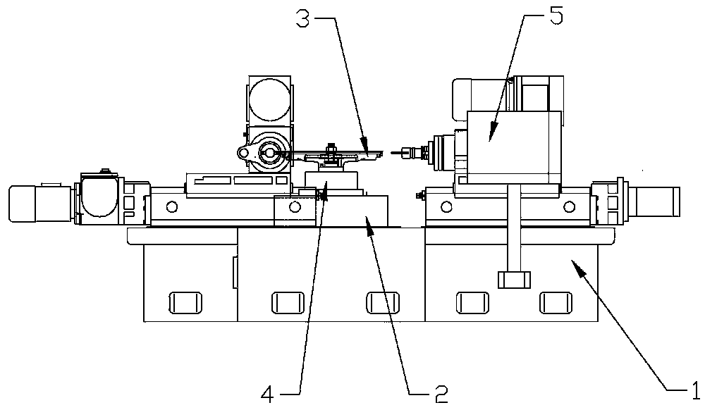
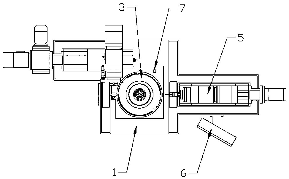
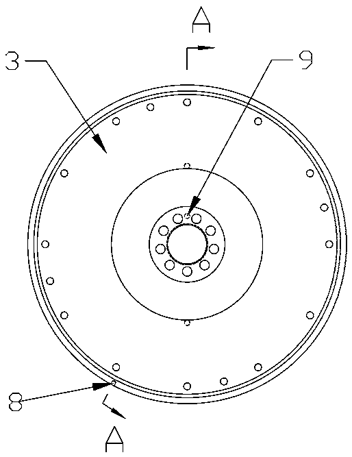
[0031] Examples such as Figure 1-4 As shown, a flywheel sensor hole inspection process, the device for implementing the process is a sensor hole processing device, the sensor hole processing device includes a base 1, a rotary table 2 is provided on the base 1, and a rotary table 2 is provided for The fixture 4 for fixing the flywheel 3 is provided with a drilling device 5 for processing sensor holes, a PLC industrial computer 6 and a display screen on the base 1, and a detection device is provided on the rotary table 2, and a signal collection sensor is provided on the detection device 7. The s...


PUM


Abstract

The invention discloses a one-hundred-percent inspection process for flywheel sensor holes. The one-hundred-percent inspection process comprises the steps: setting is carried out, specifically, parameter set values of the included angle, height and depth of the flywheel sensor holes are input into a PLC industrial personal computer, waveforms generated by the flywheel sensor holes meeting the requirement in the PLC industrial personal computer are stored, a flywheel is arranged on a clamp, a datum plane B of the flywheel is arranged downwards, a positioning pin is inserted into a positioning hole of the flywheel to fix the flywheel onto the clamp, and the distance between a signal collecting sensor and the outer edge of the flywheel is controlled to be set to be 1 + / - 0.5 mm to prevent collision to the sensor during feeding and discharging; then drilling is carried out, specifically, drilling is conducted; and inspection is carried out, inspected information is compared with the set values of the angle, the height and the depth, in the machining process of the flywheel sensor holes, the sensor simulates an ECU to inspect the problems such as included angle, height, sand hole, shrinkage porosity and collision of the sensor holes, defective components are prevented from being sent to a whole machine factory, and the quality loss is reduced.

Description

technical field [0001] The invention belongs to the technical field of internal combustion engines, and in particular relates to an inspection process and device for a flywheel sensor hole. Background technique [0002] When the diesel engine is working, the (58) sensor holes on the largest outer circle of the flywheel will generate a pulse signal through the sensor fixed on the flywheel shell, collect the signal through the ECU (engine central processing unit), and judge the position of the crankshaft to control the EFI system Send work instructions to the corresponding fuel injectors to realize the fuel supply work of the diesel engine. [0003] When the sensor hole on the outer circle of the flywheel, the angle between the holes is out of tolerance, the axial height is out of tolerance, or the outer circle has defects such as bumps and sand holes, the sensor will be misidentified as a useful signal, affecting the normal fuel supply of the engine The timing causes the eng...

Claims


Application Information

Patent Timeline
IPC IPC(8): B23Q17/20G05B19/05B23B41/00
CPCB23B41/00B23Q17/20G05B19/05
Inventor 李金年李建赵连凯
Owner SHENGRUI TRANSMISSION
Why Eureka
Try Eureka