Electrolyte station and electric power management system
A technology of electrolyte and electrolyte tank, applied in electrolyte flow processing, power system fuel cells, charging stations, etc., can solve problems such as electrolyte replacement without discussion
- Summary
- Abstract
- Description
- Claims
- Application Information
AI Technical Summary
Problems solved by technology
Method used
Image
Examples
no. 1 example
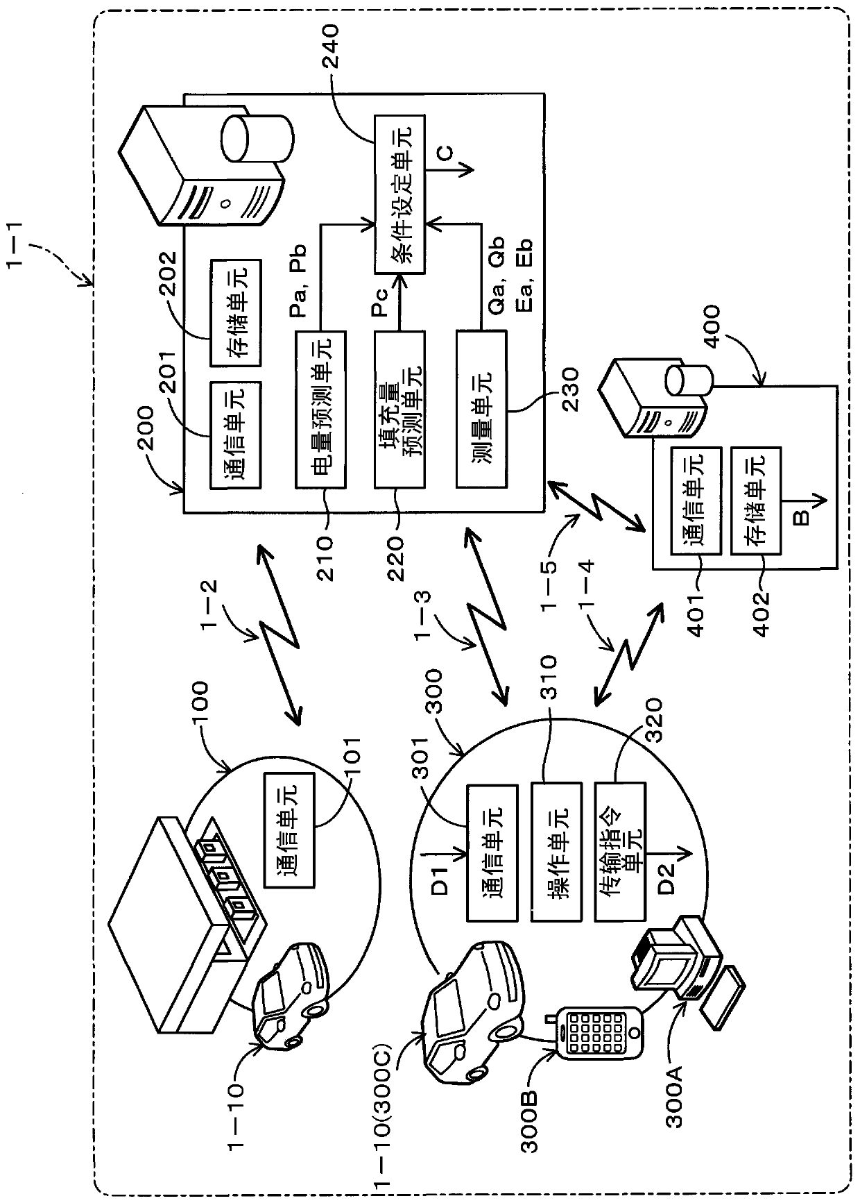
[0045] Such as figure 1 As shown, the power management system 1 - 1 according to the first embodiment includes an electrolytic solution station 100 , a management device 200 , and a terminal device 300 as constituent elements. The management device 200 and the terminal device 300 are provided separately from the electrolyte station 100 .
[0046] here, in figure 1 In , each of the constituent elements described above is shown for convenience of description. However, the number of constituent elements as described above may be appropriately changed. In addition, other constituent elements may be added to the constituent elements described above as needed.
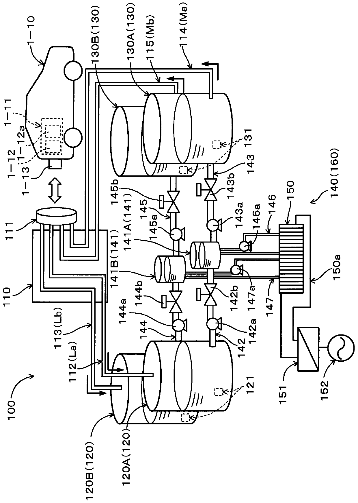
[0047] The electrolyte station 100 is used in the redox flow battery A11 installed to the vehicle A10 (see figure 2 ) in the electrolyte replacement. The electrolyte station 100 may be a dedicated station performing only replacement of electrolyte. Alternatively, the electrolyte station 100 may be a dual-purpose stati...
no. 2 example
[0138] Such as Figure 10 As shown, the electrolytic solution station 100A according to the second embodiment differs from the electrolytic solution station 100 according to the first embodiment in the charging / discharging structure connected to the battery stack 150 . The electrolyte station 100A is configured as a combination charging and electrolyte station that provides a function for charging a secondary battery installed in the connection vehicle 154 in addition to the function of the electrolyte station 100 .
[0139] Therefore, the charging processing device 140 of the electrolytic solution station 100A includes a charging and discharging device 153 in addition to the charging and discharging device 151 . The charge and discharge device 153 is configured as a charge and discharge device for a vehicle. The charging and discharging device 153 is used for charging and discharging with a connected vehicle 154 as an external connection object. The charge and discharge dev...
no. 3 example
[0171] Such as Figure 17 As shown, the energy management system 1 of the third embodiment includes a plurality of energy supply stations 10 , an energy management device 30 , a terminal device 50 , and a vehicle information server 70 as constituent elements.
[0172] here, in Figure 17 In , for convenience of description, one of each of the energy management device 30 , the terminal device 50 and the vehicle information server 70 is shown. However, the amounts of constituent elements as described above may be appropriately changed. In addition, other constituent elements may be added to the constituent elements described above as needed.
[0173] The plurality of energy supply stations 10 includes a plurality of electrolyte solution stations 10A and a plurality of charging stations 10B.
[0174] Although described in detail below, the electrolytic solution station 10A is an energy supply station including facilities capable of electrolyte replacement in the redox flow bat...
PUM
 Abstract
Description
Claims
Application Information
 - R&D
- Intellectual Property
- Life Sciences
- Materials
- Tech Scout
- Unparalleled Data Quality
- Higher Quality Content
- 60% Fewer Hallucinations
Browse by: Latest US Patents, China's latest patents, Technical Efficacy Thesaurus, Application Domain, Technology Topic, Popular Technical Reports.
© 2025 PatSnap. All rights reserved.Legal|Privacy policy|Modern Slavery Act Transparency Statement|Sitemap|About US| Contact US: help@patsnap.com


