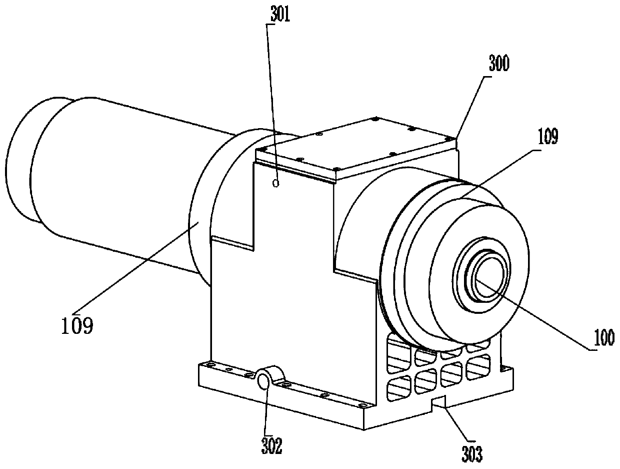
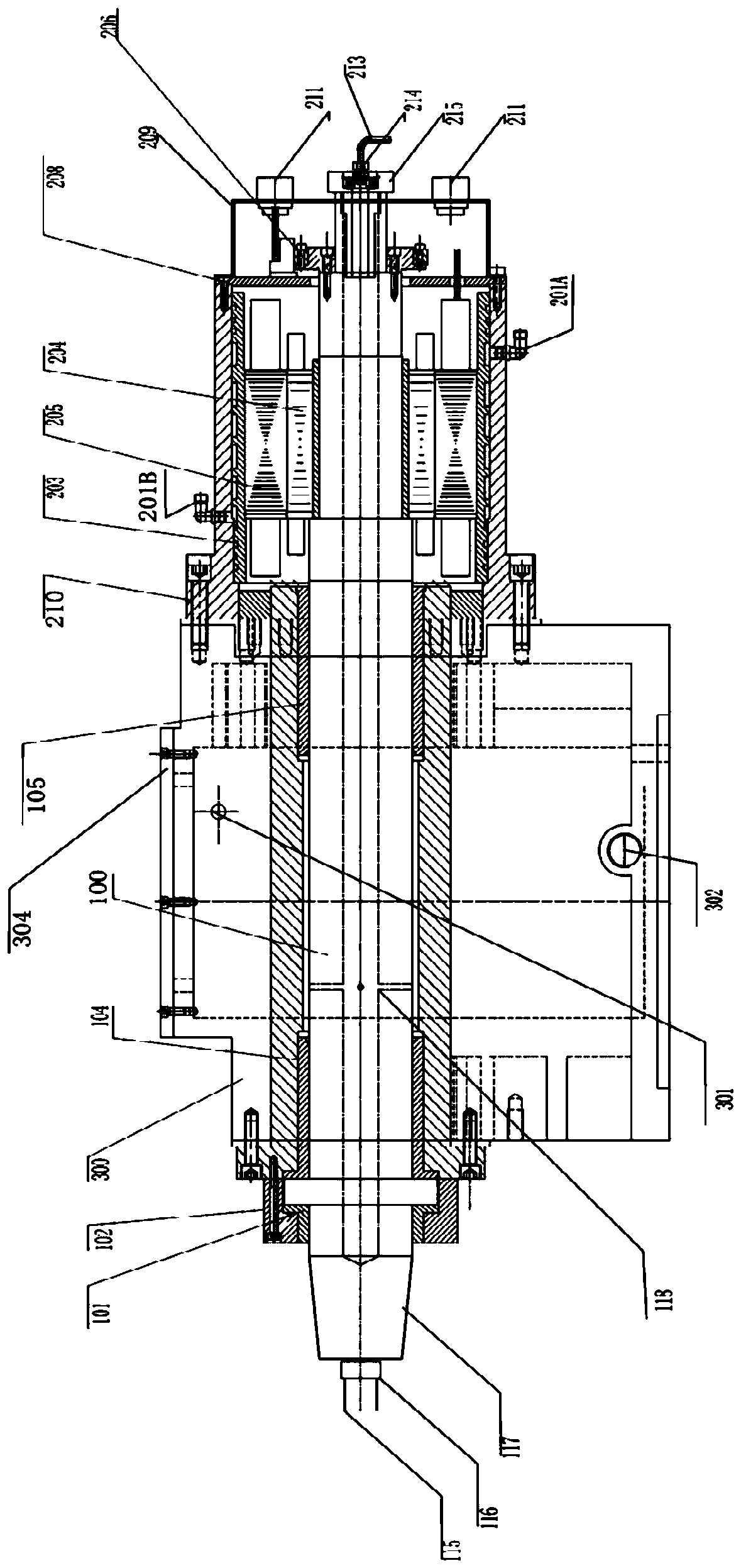
High-speed mandrel inner-cooling dynamic and static oil pressure permanent magnet servo electric spindle

A technology of permanent magnet servo motor and servo motor, applied in the direction of electromechanical devices, electrical components, electric components, etc., can solve the problems of loss of high precision, loss of rotation accuracy, loss of high rigidity, etc., and achieve effective control of thermal expansion coefficient and speed regulation The effect of widening the range and improving the wear resistance

Pending Publication Date: 2020-06-26
胡功明
View PDF4 Cites 6 Cited by
  • Summary
  • Abstract
  • Description
  • Claims
  • Application Information

AI Technical Summary

Problems solved by technology

Although it is proposed in the published patents that the spindle can reach high speed or have a wider speed range, the actual application has not achieved the stated results. The biggest technical problem is that it cannot handle the spindle at high speed. The heat generated and the thermal expansion of the metal, if you want to get a higher speed and speed regulation range, the only way is to control the temperature rise and thermal expansion of the applied material or expand the fit gap between the shaft center and the bearing. If the fit gap is large, of course you can A higher speed is obtained, but if the oil is overloaded by an external force, the rotation accuracy will be lost, and the shaft center will contact the bearing, thereby accelerating the damage to the main shaft, and at the cost of losing high rigidity and high precision, the oil pressure will be lost. The purpose of the spindle invention
If the pumping pressure of the oil pressure is continuously increased, mechanical methods cannot be used to remove the seal, resulting in oil leakage, and stress will be generated after all mechanical parts are subjected to high-pressure internal expansion force, and all shaft mechanical parts will be deformed and lose precision.

Method used


Image

  • High-speed mandrel inner-cooling dynamic and static oil pressure permanent magnet servo electric spindle
  • High-speed mandrel inner-cooling dynamic and static oil pressure permanent magnet servo electric spindle
  • High-speed mandrel inner-cooling dynamic and static oil pressure permanent magnet servo electric spindle

Examples


Embodiment Construction

[0042] In order to make the purpose, features, and advantages of the application more obvious and understandable, the technical solutions in the embodiments of the application will be clearly and completely described below in conjunction with the drawings in the embodiments of the application. Obviously, the following The described embodiments are only some of the embodiments of the present application, but not all of them. Based on the embodiments in this application, all other embodiments obtained by persons of ordinary skill in the art without making creative efforts belong to the scope of protection of this application.

[0043] The present invention will be further explained below in conjunction with the accompanying drawings and specific embodiments.

[0044] In the description of the present application, it should be understood that the orientation or positional relationship indicated by the terms "upper", "lower", "top", "bottom", "inner", "outer" etc. Orientation or ...


PUM


Abstract

The invention discloses a high-speed mandrel inner-cooling dynamic and static oil pressure permanent magnet servo electric spindle which is mainly used for a grinding machine grinding wheel shaft or ahigh-end lathe power shaft. The high-speed mandrel inner-cooling dynamic and static oil pressure permanent magnet servo electric spindle comprises a main shaft mandrel and servo motor mandrel coaxialintegrated structure, three tungsten steel sleeve (hard alloy) bearings, a main shaft shell body, a mounting main shaft box body, a servo motor rotor, a stator, a servo motor hollow encoder and an oil supply pipeline. According to the high-speed mandrel inner-cooling dynamic and static oil pressure permanent magnet servo electric spindle, the innovation lies in that the tungsten steel sleeve (hard alloy) bearings are applied, the thermal expansion coefficient is effectively controlled, the wear resistance is improved, a spindle mandrel hollow refrigeration reflux circulating device is added,a constant temperature controller is added, and the temperature rise deformation of the mandrel is effectively controlled, so that the known rotation speed regulation range of the dynamic and static oil pressure permanent magnet servo electric spindle is widened, and under the condition that high precision and high rigidity are not lost, a higher rotating speed is achieved.

Description

technical field [0001] The present application relates to the technical field of high-precision dynamic and static oil piezoelectric spindles, in particular to a dynamic and static hydraulic permanent magnet servo electric spindle with internal cooling of a high-speed mandrel. Background technique [0002] The hydrodynamic and static pressure mechanical spindle is a high-tech product developed in the 1980s in my country with the world's advanced level. The most commonly used and known dynamic and static hydraulic spindle is mainly composed of mechanical structure units. The power source is mainly an electric motor through the known method of a pulley. connect. There are also those that directly connect the main shaft of the dynamic and static pressure machinery with the motor, and those that disassemble the rotor and stator of the motor and install them in the middle of the shaft of the dynamic and static hydraulic machinery. A series of technical problems such as weight, vo...

Claims


Application Information

Patent Timeline
IPC IPC(8): B23B19/02B24B5/35B24B41/04B24B45/00B24B55/00H02K7/00
CPCB23Q1/70B24B5/35B24B41/04B24B45/003B24B55/00H02K7/00H02K7/003
Inventor 胡功明
Owner 胡功明
Why Eureka
Try Eureka