Movable diversion device for debris flow interception

A diversion device and mud-rock flow technology, applied in water conservancy projects, dikes, sea area engineering, etc., can solve problems such as unsatisfactory mud-rock flow effects, achieve strong geological disaster resistance, reduce impact and destructive effects

Pending Publication Date: 2020-06-26
段刚强
View PDF12 Cites 6 Cited by
  • Summary
  • Abstract
  • Description
  • Claims
  • Application Information

AI Technical Summary

Problems solved by technology

[0006] In order to solve the problem of unsatisfactory prevention and control of debris flow in the existing method of setting up interception dams, the present invention provides a movable diversion device for intercepting debris flow, the core of which is a silt stop diversion dam and two movable diversion mechanisms. While dividing the debris flow into two streams, the dam has built several new silting zones, which can slow down, settle and partially stagnate the debris flow. The movable diversion mechanism can automatically determine whether part of the debris flow is needed according to the flow of the debris flow. Interception, when the flow of debris flow is large, the movable diversion mechanism is pushed to deflect, and then the debris flow is filtered and diverted, and part of the filtered debris flow is diverted to the silting area for storage, thereby reducing the flow rate of the debris flow and greatly reducing the flow rate of the debris flow. The impact force and destructiveness of debris flow, and the blocking system has a strong ability to resist geological disasters, even if some damage occurs, it will not have a great impact on the prevention and control effect

Method used


Image

  • Movable diversion device for debris flow interception
  • Movable diversion device for debris flow interception
  • Movable diversion device for debris flow interception

Examples


Embodiment 1

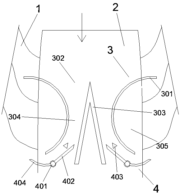
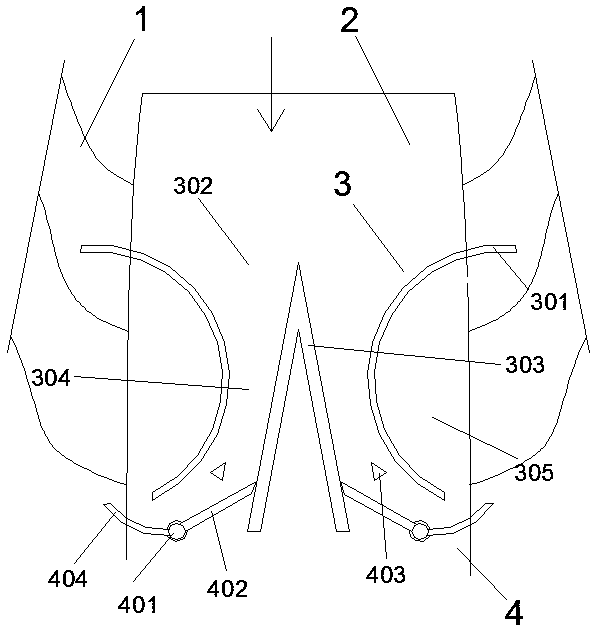
[0038] Such as figure 1 and 2 As shown, a movable diversion device for intercepting debris flow is arranged in the debris flow channel 2 formed between the highlands 1 on both sides. The movable diverter device includes a silting diversion dam 3 and two movable Type diversion mechanism 4, wherein, the silting and diversion dam 3 includes the first arc-shaped dam body 301 symmetrically arranged on both sides of the debris flow channel 2, and the upstream ends of the two first arc-shaped dam bodies 301 respectively cross the debris flow channel The two sides of 2 are connected to the high grounds 1 on both sides, and there is a gap between the downstream end and the two sides of the debris flow channel 2, so that the backwater surface of the two first arc-shaped dam bodies 301 cooperates with the high grounds 1 on both sides to form a The silting zone 305 that opens toward the downstream direction; a hyperbolic drainage channel 302 is formed between the two first arc-shaped dam...

Embodiment 2

[0045] This embodiment is an improvement made on the basis of Embodiment 1, its basic structure is the same as that of Embodiment 1, and the improvements are as follows: figure 1 and 2 As shown, the first diversion plate 402 is provided with a limit pile 403 to limit its deflection to the side of the diversion dam 303 toward the side of the first arc-shaped dam body 301 on this side, and the limit pile 403 is a triangular cement pile. And one of the sharp corners of its triangle faces the direction of the debris flow. The bottom of the first diversion plate 402 and the second diversion plate 404 are provided with several support columns along their length direction, the bottom end of each support column has a spherical support 405 supported on the ground, the spherical support 405 is actually The upper part is a sphere supported by cement concrete, so that the contact area with the ground is small, and it can be rotated conveniently when being impacted by debris flow; a diver...

Embodiment 3

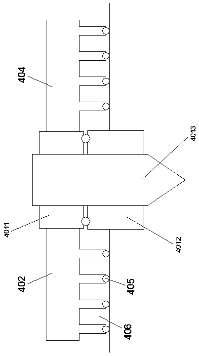
[0047] This embodiment is another improvement made on the basis of embodiment 1, its basic structure is the same as that of embodiment 1, and the improvements are as follows: image 3 As shown, the rotator 401 includes a rotating base 4011 connecting the first flow guide plate 402 and the second flow guide plate 404. The rotation base 4011 is a disc, and the disc is rotated by a number of second balls provided on its bottom surface. On the fixed base 4012, the lower part of the fixed base 4012 is buried in the ground, and a corresponding through hole is provided at the center of the rotating base 4011 and the fixed base 4012, and a rotating shaft 4013 is provided in the through hole, the rotation The shaft 4013 is wedged into the ground through the tip of its bottom end, so that the rotating base 4011 forms a rotating part that can rotate around the rotating shaft 4013 .

[0048] In fact, the rotator 401 is a structure similar to a stone mill. Two stone mills can rotate relati...


PUM


Abstract

The invention relates to a movable diversion device for debris flow interception. The movable diversion device is arranged in a debris flow passage formed between highlands on two sides and comprisesa stopping and silting diversion dam and two movable flow guidance mechanisms. The stopping and silting diversion dam divides the debris flow into two streams and constructs multiple new stopping andsilting areas, so that the debris flow can slow down, settle down and partially stop. The movable flow guidance mechanisms can automatically judge whether partial interception is required according tothe flow size of the debris flow. When the flow of the debris flow is large, the movable flow guidance mechanisms are pushed to deflect to filter and divert the debris flow, and guide part of the filtered debris flow into the stopping and silting areas for storage. Therefore, the flow of the debris flow is reduced, and the impact and destructiveness of the debris flow are greatly reduced. Moreover, an interception system has strong resistance to geological hazards. Even if partial damage occurs, the prevention and control effect cannot be greatly affected.

Description

technical field [0001] The invention relates to the field of prevention and control of geological disaster mud-rock flow, in particular to a movable diversion device for intercepting mud-rock flow. Background technique [0002] Debris flow refers to a special torrent carrying a large amount of sediment and stones due to landslides caused by heavy rain or other natural disasters in mountainous areas or other areas with deep valleys and steep terrain. Debris flow has the characteristics of suddenness, fast flow rate, large flow rate, large material capacity and strong destructive force. Debris flows often destroy highways, railways and other transportation facilities and even villages and towns, causing huge losses. [0003] The whole process of debris flow generally only takes a few hours, and the shortest is only a few minutes. It is a natural disaster widely distributed in some countries with special topography and landform conditions. This is a mixed flow of soil, water ...

Claims


Application Information

Patent Timeline
Patent Type & Authority Applications(China)
IPC IPC(8): E02B3/10E02B8/06
CPCE02B3/10E02B8/06
Inventor 段刚强唐巧雪杨宁苛其他发明人请求不公开姓名
Owner 段刚强
Why Eureka
Try Eureka