Gasification furnace capable of achieving sufficient burning
A technology for sufficient combustion and gasifier, applied in the field of gasifier, can solve the problem of insufficient combustion of biofuel, and achieve the effects of improving adequacy, reducing occupancy rate, and avoiding fuel accumulation
- Summary
- Abstract
- Description
- Claims
- Application Information
AI Technical Summary
Problems solved by technology
Method used
Image
Examples
Embodiment 1
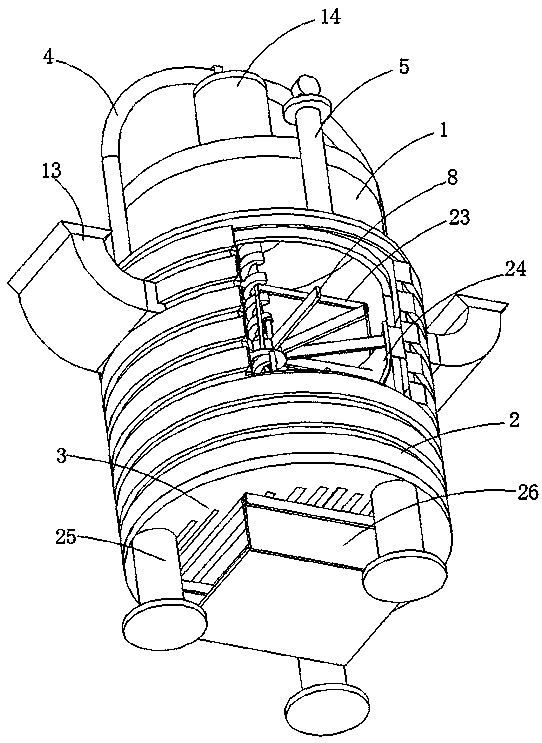
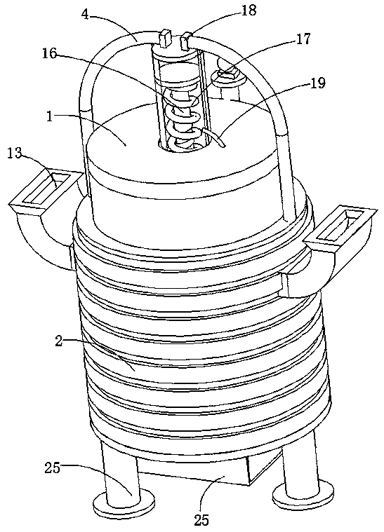
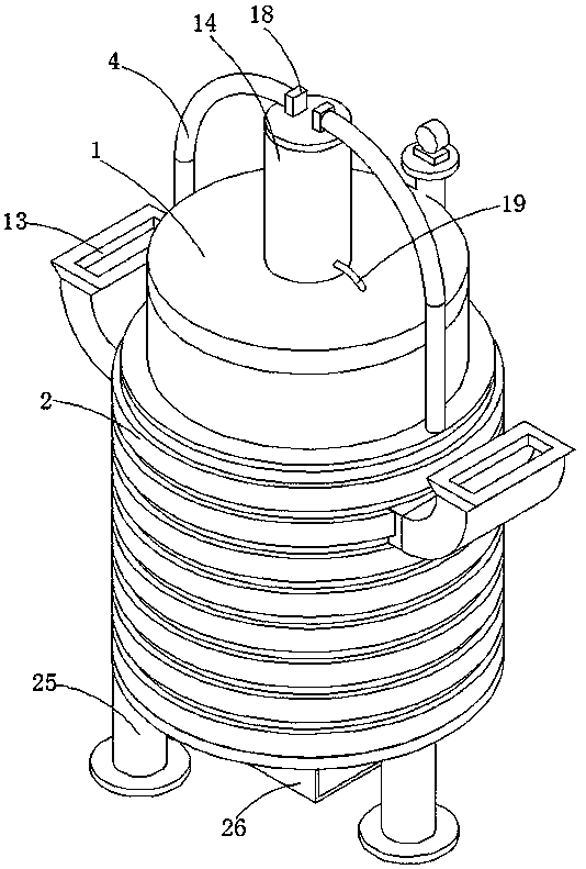
[0031] refer to Figure 1-5 , a fully combusted gasifier, comprising a furnace body 1 and a heat preservation shell 2, a water storage layer is arranged between the furnace body 1 and the heat preservation shell 2, a fire grate 3 is fixedly connected to the bottom of the furnace body 1, and the heat preservation shell 2 The top is connected with the steam generation pipe 4 and the heat supply pipe 5 which are connected with the aquifer, and the end of the steam generation pipe 4 away from the insulation shell 2 is connected with a lifting mechanism placed on the top of the furnace body 1, and the movable end of the lifting mechanism is connected with a Place the screw mandrel 6 in the furnace body 1, the outer wall of the screw mandrel 6 is fixedly connected with the first fluffy frame 8 through the fixing ring 7, and the outer wall of the screw mandrel 6 is also slidably connected with the second fluffy frame 8 placed below the first The fluffy frame 9 is slidably connected w...
Embodiment 2
[0040] refer to Figure 1-3 , a fully combusted gasifier, which is basically the same as in Embodiment 1, furthermore, the end of the pressure relief pipe 19 away from the cylinder body 14 is placed in the furnace body 1;
[0041] The steam enters the furnace body 1 to provide oxygen for the further combustion of the fuel and the flue gas produced by fuel combustion, further improving the adequacy of fuel combustion.
Embodiment 3
[0043] refer to Figure 1-5 , the fully combusted gasifier is basically the same as in Example 1, and furthermore, the outer wall of the screw rod 6 between the fixed ring 7 and the lifting mechanism is also fixedly connected with a U-shaped frame 23, and the vertical position of the U-shaped frame 23 The section is connected with a baffle plate 24, and the baffle plate 24 matches with the feed port on the feed bin 13;
[0044] The water in the aquifer is gradually heated until it boils, and then the steam flows from the aquifer to the steam generating pipe 4, and the steam flowing to the steam generating pipe 4 flows into the cylinder 14 through the intake valve 18, and flows into the cylinder 14 The amount of steam increases, the piston 15 drives the transmission rod 16 to squeeze the return spring 17, and as the return spring 17 continues to tighten, the transmission rod 16 drives the screw rod 6 to move down, driving the U-shaped frame 23 to move down, and at this time the...
PUM
 Abstract
Description
Claims
Application Information
 - R&D
- Intellectual Property
- Life Sciences
- Materials
- Tech Scout
- Unparalleled Data Quality
- Higher Quality Content
- 60% Fewer Hallucinations
Browse by: Latest US Patents, China's latest patents, Technical Efficacy Thesaurus, Application Domain, Technology Topic, Popular Technical Reports.
© 2025 PatSnap. All rights reserved.Legal|Privacy policy|Modern Slavery Act Transparency Statement|Sitemap|About US| Contact US: help@patsnap.com


