Display panel, display device and pixel driving method
A display panel and pixel technology, applied in static indicators, instruments, etc., can solve problems such as affecting the screen display effect, increasing the power consumption of light-emitting diodes, and OLED current instability.
Active Publication Date: 2020-06-30
BOE TECH GRP CO LTD +1
10 Cites 2 Cited by
AI-Extracted Technical Summary
Problems solved by technology
[0005] However, due to the parasitic capacitance between the gate and the drain of the switching thin film transistor, this will cause the source of the switching thin film transistor to change due to the change of the drain voltage of the switching thin film transistor when the switching thin fi...
Abstract
The invention provides a display panel, a display device and a pixel driving method. In the display panel, each row of sub-pixels is correspondingly connected with at least one voltage switching circuit, each voltage switching circuit comprises a first voltage switching sub-circuit and a second voltage switching sub-circuit, the first voltage switching sub-circuit is configured to control a threshold compensation circuit of the sub-pixel of the corresponding row to work or not to work when a scanning line of the corresponding row controls the threshold compensation circuit of the sub-pixel ofthe corresponding row, responding to the control of the scanning line of the corresponding row, different power supply positive voltages are provided for a power supply positive voltage end of the rowof sub-pixels, and the second voltage switching sub-circuit is configured to provide different power supply negative voltages for a power supply negative voltage end of the row of sub-pixels in response to the control of the scanning line of the corresponding row when the scanning line of the corresponding row controls the threshold compensation circuit of the sub-pixel of the corresponding row to work or not work. Therefore, the display effect of the display panel is effectively improved, and meanwhile it is guaranteed that the power consumption of the display panel is not changed.
Application Domain
Static indicating devices
Technology Topic
Hemt circuitsScan line +4
Image
Examples
- Experimental program(1)
Example Embodiment
[0042] In order to enable those skilled in the art to better understand the technical solutions of the embodiments of the present disclosure, the technical solutions of the display panel, display device, and pixel driving method provided by the embodiments of the present disclosure will be clarified below in conjunction with the drawings of the embodiments of the present disclosure. , Complete description.
[0043] Hereinafter, example embodiments will be described more fully with reference to the accompanying drawings, but the example embodiments may be embodied in different forms and should not be construed as being limited to the embodiments set forth herein. On the contrary, the purpose of providing these embodiments is to make the present disclosure thorough and complete, and to enable those skilled in the art to fully understand the scope of the present disclosure.
[0044] The terms used herein are only used to describe specific embodiments and are not intended to limit the present disclosure. As used herein, the singular forms "a" and "the" are also intended to include the plural forms, unless the context clearly dictates otherwise. It will also be understood that when the terms "including" and/or "comprising" are used in this specification, it specifies the presence of the described features, wholes, steps, operations, elements and/or components, but does not exclude the presence or addition of one or more Other features, wholes, steps, operations, elements, components and/or groups thereof.
[0045] It will be understood that although the terms first, second, etc. may be used herein to describe various elements/structures, these elements/structures should not be limited by these terms. These terms are only used to distinguish one element/structure from another element/structure.
[0046] Unless otherwise defined, all terms (including technical and scientific terms) used herein have the same meanings as commonly understood by those of ordinary skill in the art. It will also be understood that terms such as those defined in commonly used dictionaries should be interpreted as having meanings consistent with their meanings in the context of the related technology and the present disclosure, and will not be interpreted as having idealized or excessive formal meanings, Unless this article specifically defines it as such.
[0047] It should be noted that the transistors in the embodiments of the present disclosure may be thin film transistors or field effect transistors or other switching devices with the same characteristics. A transistor generally includes three electrodes: a gate, a source, and a drain. The source and drain in the transistor are structurally symmetrical, and the two can be interchanged as needed. In the embodiments of the present disclosure, the control electrode refers to the gate of the transistor, and one of the first electrode and the second electrode is the source and the other is the drain. In addition, according to the characteristics of transistors, transistors can be divided into N-type transistors and P-type transistors; when the transistor is an N-type transistor, its turn-on voltage is a high-level voltage, and its cut-off voltage is a low-level voltage; when the transistor is a P In the case of a type transistor, its turn-on voltage is a low-level voltage, and its turn-off voltage is a high-level voltage.
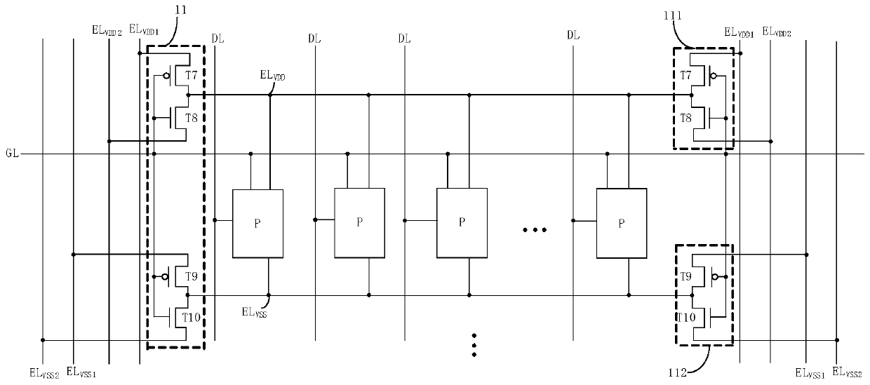
[0048] figure 1 A schematic structural diagram of a display panel provided by an embodiment of the present disclosure, such as figure 1 As shown, in the embodiment of the present disclosure, the display panel includes a display area and a non-display area located at the periphery of the display area, and the display area includes a plurality of sub-pixels P arranged in an array. Among them, in some embodiments, each row of sub-pixels P may include sub-pixels of three colors: red sub-pixel (R), green sub-pixel (G), and blue sub-pixel (B). In some embodiments, It may further include a white sub-pixel (W).
[0049] It should be noted, figure 1 Only one row of sub-pixels P is shown in exemplarily. The embodiments of the present disclosure include but are not limited to this. The display panel in the embodiments of the present disclosure may also include more rows and more columns of sub-pixels P.
[0050] Such as figure 1 As shown, in the embodiment of the present disclosure, the display area further includes a plurality of scan lines (also called gate lines) GL extending in the row direction and a plurality of data lines DL extending in the column direction, wherein the scan lines GL and The data lines DL are arranged crosswise and define sub-pixels P. In the embodiment of the present disclosure, each column of sub-pixels P is connected to a column of data lines DL, and each row of sub-pixels P is connected to a row of scan lines GL. Wherein, the scan line GL is used to provide a gate scan signal to the correspondingly connected sub-pixel P, and the data line DL is used to provide the required data voltage Vdata to the correspondingly connected sub-pixel P.
[0051] It should be noted, figure 1 Only exemplarily shows that each row of scan lines GL corresponds to one row of sub-pixels P, and each column of data lines DL corresponds to one column of sub-pixels P. The embodiments of the present disclosure include but are not limited to this, for example, in some embodiments , It may also be that each row of sub-pixels P corresponds to two rows of scan lines GL, in each row of sub-pixels, some of the sub-pixels P are connected to the corresponding row of scan lines GL, and the other portion of sub-pixels P is connected to another row of scan lines GL. connection.
[0052] Such as figure 1 As shown, in the embodiment of the present disclosure, the non-display area includes multiple voltage switching circuits, each row of sub-pixels is correspondingly connected to at least one voltage switching circuit 11, and the voltage switching circuit 11 corresponding to each row of sub-pixels is connected to the corresponding row of sub-pixels. For the scan line GL, each voltage switching circuit 11 includes a first voltage switching sub-circuit 111 and a second voltage switching sub-circuit 112.
[0053] Such as figure 1 As shown, in the embodiment of the present disclosure, the non-display area further includes a plurality of power supply lines extending along the column direction, wherein the plurality of power supply lines includes the first power supply positive voltage line EL VDD1 , The second power supply positive voltage line EL VDD2 , The first power supply negative voltage line EL VSS1 , The second power supply negative voltage line EL VSS2.
[0054] In some embodiments, such as figure 1 As shown, each row of sub-pixels P is connected to two voltage switching circuits 11, and the two voltage switching circuits 11 are respectively located on both sides of the row of sub-pixels P, correspondingly, the first power supply positive voltage line EL VDD1 , The second power supply positive voltage line EL VDD2 , The first power supply negative voltage line EL VSS1 , The second power supply negative voltage line EL VSS2 The number of is two respectively, and they are located on both sides of the sub-pixel P in the row. It should be noted, figure 1 Only the situation where each row of sub-pixels P is connected to two voltage switching circuits 11 is shown by way of example. The embodiments of the present disclosure include but are not limited to this. For example, in some embodiments, each row of sub-pixels P may correspond to Connect a voltage switching circuit 11.
[0055] In the embodiment of the present disclosure, the display panel is applied to a display device. In the display device, the non-display area located on one side of the display area further includes a driver IC (Integrated Circuit, integrated circuit) (not shown in the figure). Power supply positive voltage line EL VDD1 , The second power supply positive voltage line EL VDD2 , The first power supply negative voltage line EL VSS1 , The second power supply negative voltage line EL VSS2 Are respectively connected to the driver IC, the driver IC is used to provide the first power supply positive voltage line EL VDD1 Provide the required first power supply positive voltage VDD1 to the second power supply positive voltage line EL VDD2 Provide the required second power supply positive voltage VDD2 to the first power supply negative voltage line EL VSS1 Provide the required first power negative voltage VSS1 to the second power negative voltage line EL VSS2 Provide the required second power negative voltage VSS2.
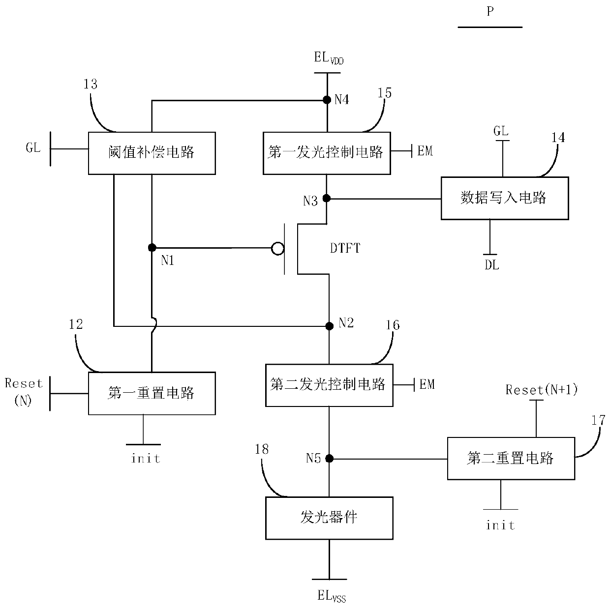
[0056] figure 2 for figure 1 A schematic diagram of the structure of a sub-pixel in figure 2 As shown, in the embodiment of the present disclosure, each sub-pixel P includes a first reset circuit 12, a threshold compensation circuit 13, a data writing circuit 14, a first light emission control circuit 15, a second light emission control circuit 16, and a second Set circuit 17, drive transistor DTFT and light emitting device 18. Among them, the light-emitting device 18 may be a current-driven light-emitting device, such as an OLED light-emitting device, an AMOLED (Active-Matrix Organic Light-Emitting Diode, active-matrix organic light-emitting diode) light-emitting device, a micro light-emitting diode (Micro LED), and a mini light-emitting diode. (Mini LED). In this disclosure, the light-emitting device 18 is an OLED as an example for description.
[0057] Such as figure 2 As shown, the first reset circuit 12 is connected to the first reset control terminal Reset(N), the control electrode of the driving transistor DTFT (ie, the first node N1), and the reset voltage terminal init, and the first reset circuit 12 is configured as In response to the control of the first reset control terminal Reset(N), the reset voltage Vinit provided by the reset voltage terminal init is written to the control electrode of the driving transistor DTFT (ie, the first node N1), so as to control the driving transistor DTFT The potential of the control electrode (ie, the first node N1) is reset.
[0058] Such as figure 2 As shown, the second reset circuit 17 is connected to the second reset control terminal Reset(N+1), the first pole of the light-emitting device 18 (that is, the fifth node N5) and the reset voltage terminal init, and the second reset circuit 17 Is configured to write the reset voltage Vinit provided by the reset voltage terminal init to the first pole (that is, the fifth node N5) of the light emitting device 18 in response to the control of the second reset control terminal Reset(N+1), The first pole of the light emitting device 18 (ie, the fifth node N5) is reset.
[0059] Such as figure 2 As shown, the data writing circuit 14 is connected to the corresponding scan line GL, the first pole of the driving transistor DTFT (that is, the third node N3), and the corresponding data line DL, and the data writing circuit 14 is configured to respond to the corresponding scan The line GL is controlled to write the data voltage Vdata provided by the corresponding data line DL to the first pole of the driving transistor DTFT (ie, the third node N3).
[0060] Such as figure 2 As shown, the threshold compensation circuit 13 and the power supply positive voltage terminal EL VDD The control electrode of the driving transistor DTFT (ie the first node N1), the corresponding scan line GL and the second electrode of the driving transistor DTFT (ie the second node N2) are connected, and the threshold compensation circuit 13 is configured to respond to the corresponding scan line In the control of GL, the compensation voltage is written to the control electrode of the driving transistor DTFT (ie, the first node N1), and the compensation voltage is equal to the sum of the data voltage Vdata and the threshold voltage Vth of the driving transistor DTFT.
[0061] Such as figure 2 As shown, the first light-emitting control circuit 15 and the power supply positive voltage terminal EL VDD , The first pole of the driving transistor DTFT (that is, the third node N3) is connected to the emission control terminal EM, and the first emission control circuit 15 is configured to respond to the control of the emission control signal provided by the emission control terminal EM to turn the power supply positive voltage End EL VDD The supplied voltage is written to the first pole of the driving transistor DTFT (ie, the third node N3).
[0062] Such as figure 2 As shown, the second light emission control circuit 16 is connected to the light emission control terminal EM, the second pole of the driving transistor DTFT (ie, the second node N2), and the first pole (ie, the fifth node N5) of the light emitting device 18, and the second light emission control The circuit 16 is configured to respond to the control of the emission control signal provided by the emission control terminal EM to drive the second pole of the transistor DTFT (ie, the second node N2) and the first pole of the light emitting device 18 (ie, the fifth node N5) Conduction.
[0063] Such as figure 2 As shown, the driving transistor DTFT is configured to respond to the control of the compensation voltage provided by the first node N1 and output a corresponding driving current to the light emitting device 18 through the second light emitting control circuit 16 to drive the light emitting device 18 to emit light. Among them, the second pole of the light-emitting device 18 and the negative voltage terminal EL of the power supply VSS connection.
[0064] Such as figure 1 with figure 2 As shown, the first voltage switching sub-circuit 111 and the first power supply positive voltage line EL VDD1 , The second power supply positive voltage line EL VDD2 , The scan line GL corresponding to one row and the positive voltage terminal EL of the power supply of the sub-pixels corresponding to one row VDD connection. The first voltage switching sub-circuit 111 is configured to switch the first power supply positive voltage line EL in response to the control of the correspondingly connected scan line GL when the scan line GL connected to it controls the threshold compensation circuit 13 to operate VDD1 The provided first power supply positive voltage VDD1 is written to the corresponding power supply positive voltage terminal EL VDD The first voltage switching sub-circuit 111 is also configured to control the threshold compensation circuit 13 by the scan line GL connected to it in response to the control of the scan line GL connected to the second power supply positive voltage line EL VDD2 The provided second power supply positive voltage VDD2 is written to the corresponding power supply positive voltage terminal EL VDD. Wherein, the second power supply positive voltage VDD2 is greater than the first power supply positive voltage VDD1.
[0065] Such as figure 1 with figure 2 As shown, the second voltage switching sub-circuit 112 and the first power negative voltage line EL VSS1 , The second power supply negative voltage line EL VSS2 , The scan line GL corresponding to one row and the negative power supply terminal EL of the sub-pixels corresponding to one row VSS connection. The second voltage switching sub-circuit 112 is configured to switch the first power supply negative voltage line EL in response to the control of the correspondingly connected scan line GL when the scan line GL connected to it controls the threshold compensation circuit 13 to operate. VSS1 The provided first power negative voltage VSS1 is written to the corresponding power negative voltage terminal EL VSS The second voltage switching sub-circuit 112 is also configured to control the threshold compensation circuit 13 by the scan line GL connected to it in response to the control of the scan line GL connected to the second power supply negative voltage line EL VSS2 The provided second power negative voltage VSS2 is written to the corresponding power negative voltage terminal EL VSS. Wherein, the absolute value of the first power supply negative voltage VSS1 is greater than the absolute value of the second power supply negative voltage VSS2.
[0066] In the embodiment of the present disclosure, the non-display area further includes a gate drive circuit (not shown in the figure) and a data drive circuit (not shown in the figure). The gate drive circuit is connected to each scan line GL, and the gate drive circuit It is used to provide scanning signals to each scanning line GL; the data driving circuit is connected to each data line DL, and the data driving circuit is used to provide a data voltage Vdata to each data line DL.
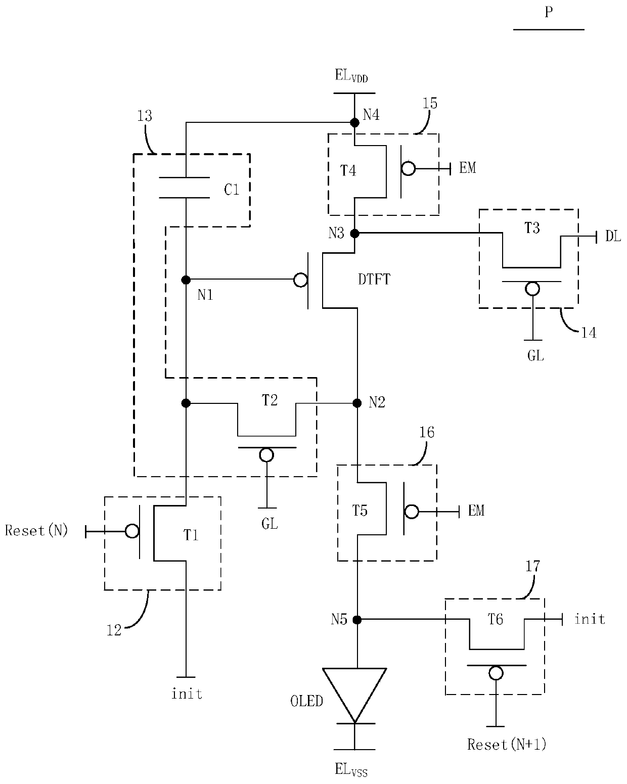
[0067] image 3 for figure 2 A schematic structural diagram of a specific implementation of sub-pixels in image 3 Shows the pixel drive circuit of each sub-pixel, such as image 3 As shown, in some embodiments, the first reset circuit 12 includes a first transistor T1, a first electrode of the first transistor T1 is connected to the reset voltage terminal init, and a second electrode of the first transistor T1 is connected to the driving transistor DTFT. The control electrode N1 is connected, and the control electrode of the first transistor T1 is connected to the first reset control terminal Reset(N).
[0068] In some embodiments, the threshold compensation circuit 13 includes a second transistor T2 and a storage capacitor C1; wherein, the first electrode of the second transistor T2 is connected to the second electrode N2 of the driving transistor DTFT, and the second electrode of the second transistor T2 is connected to The control electrode N1 of the driving transistor DTFT is connected, and the control electrode of the second transistor T2 is connected to the corresponding scan line GL; the first terminal of the storage capacitor C1 is connected to the positive voltage terminal EL of the power supply VDD Connected, the second end of the storage capacitor C1 is connected to the control electrode N1 of the driving transistor DTFT.
[0069] It can be understood that the aforementioned "scan line GL controls the threshold compensation circuit 13 to work" means that the scan line GL controls the second transistor T2 to turn on, and the aforementioned "scan line GL controls the threshold compensation circuit 13 to not work" means that the scan line GL controls the second transistor T2. The second transistor T2 is turned off.
[0070] In some embodiments, the data writing circuit 14 includes a third transistor T3, the first electrode of the third transistor T3 is connected to the corresponding data line DL, and the second electrode of the third transistor T3 is connected to the first electrode N3 of the driving transistor DTFT. Connected, the control electrode of the third transistor T3 is connected to the corresponding scan line GL.
[0071] In some embodiments, the first light emission control circuit 15 includes a fourth transistor T4, and the first electrode of the fourth transistor T4 is connected to the power supply positive voltage terminal EL. VDD The second electrode of the fourth transistor T4 is connected to the first electrode N3 of the driving transistor DTFT, and the control electrode of the fourth transistor T4 is connected to the light emitting control terminal EM.
[0072] In some embodiments, the second light emission control circuit 16 includes a fifth transistor T5, the first electrode of the fifth transistor T5 is connected to the second electrode N2 of the driving transistor DTFT, and the second electrode of the fifth transistor T5 is connected to the light emitting device OLED. The first pole N5 is connected, and the control pole of the fifth transistor T5 is connected to the emission control terminal EM.
[0073] In some embodiments, the second reset circuit 17 includes a sixth transistor T6, the first electrode of the sixth transistor T6 is connected to the reset voltage terminal init, and the second electrode of the sixth transistor T6 is connected to the first electrode of the light emitting device OLED. N5 is connected, and the control electrode of the sixth transistor T6 is connected to the second reset control terminal Reset (N+1).
[0074] In some embodiments, such as Figure 1 to Figure 3 As shown, the first voltage switching sub-circuit 111 includes a seventh transistor T7 and an eighth transistor T8; wherein, the first pole of the seventh transistor T7 is connected to the first power supply positive voltage line EL VDD1 Connected, the second electrode of the seventh transistor T7 is connected to the positive voltage terminal EL of the power supply of the sub-pixel P corresponding to one row VDD Connected, the control electrode of the seventh transistor T7 is connected to the scan line GL corresponding to one row; the first electrode of the eighth transistor T8 is connected to the second power supply positive voltage line EL VDD2 The second pole of the eighth transistor T8 is connected to the positive voltage terminal EL of the power supply of the sub-pixel P corresponding to one row VDD Connected, the control electrode of the eighth transistor T8 is connected to the scan line GL of the corresponding row.
[0075] In some embodiments, such as Figure 1 to Figure 3 As shown, the second voltage switching sub-circuit 112 includes a ninth transistor T9 and a tenth transistor T10; wherein, the first pole of the ninth transistor T9 is connected to the first negative voltage line EL of the power supply. VSS1 Connected, the second pole of the ninth transistor T9 is connected to the negative power supply terminal EL of the sub-pixel P corresponding to one row VSS Connected, the control electrode of the ninth transistor T9 is connected to the scan line GL corresponding to one row; the first electrode of the tenth transistor T10 is connected to the second power negative voltage line EL VSS2 Connected, the second pole of the tenth transistor T10 is connected to the negative power supply terminal EL of the sub-pixel P corresponding to one row VSS Connected, the control electrode of the tenth transistor T10 is connected to the scan line GL of the corresponding row.
[0076] In some embodiments, one of the seventh transistor T7 and the eighth transistor T8 is a P-type transistor, and the other is an N-type transistor. For example, the seventh transistor T7 is a P-type transistor, and the eighth transistor T8 is an N-type transistor. Transistor. One of the ninth transistor T9 and the tenth transistor T10 is a P-type transistor, and the other is an N-type transistor. For example, the ninth transistor T9 is a P-type transistor, and the tenth transistor T10 is an N-type transistor.
[0077] In some embodiments, when the seventh transistor T7 and the ninth transistor T9 are P-type transistors, the first transistor T1 to the sixth transistor T6 and the driving transistor DTFT are also P-type transistors. In some embodiments, when the seventh transistor T7 and the ninth transistor T9 are N-type transistors, the first transistor T1 to the sixth transistor T6 and the driving transistor DTFT are also N-type transistors.
[0078] Figure 4 for image 3 A working timing diagram of the pixel driving circuit shown, such as Figure 1 to Figure 4 As shown, in the embodiment of the present disclosure, the light emission of the display panel can be realized by turning on the light emission row by row. The light emission of each row of sub-pixels P is controlled by the pixel drive circuit of that row. When the pixel drive circuit of each row is turned on, the other rows of The pixel drive circuit is off. The display period of each row of sub-pixels P may include an initialization phase t1, a data writing and compensation phase t2, and a light-emitting phase t3, that is, the working process of the pixel driving circuit of each row of sub-pixels P includes: initialization phase t1, data writing And compensation phase t2, light-emitting phase t3.
[0079] In the following description, the first transistor T1 to the seventh transistor T7, the driving transistor DTFT, and the ninth transistor T9 are all P-type transistors, and the eighth transistor T8 and the tenth transistor T10 are all N-type transistors as an example. In this case, it can be understood that T1~T7, DTFT, and T9 are turned on under their control extremely low level state, and turned off under their control extremely high level state. On the contrary, T8, T10 are under their control It is turned on in an extremely high level state, and turned off in its control extremely low state.
[0080] In the initialization phase t1, the first reset control terminal Reset(N) provides a low level signal, the second reset control terminal Reset(N+1) provides a high level signal, and the scan signal provided by the scan line GL is a high level signal. The light-emitting control terminal EM provides a high-level signal.
[0081] At this time, under the control of the low-level signal provided by the first reset control terminal Reset(N), the first transistor T1 is turned on, and the reset voltage Vinit provided by the reset voltage terminal init passes through the turned-on first transistor T1 Write to the first node N1 (the control electrode of the driving transistor DTFT, the second end of the storage capacitor C1) to realize the reset process of the control electrode of the driving transistor DTFT. At the same time, since the second reset control terminal Reset (N+1), the scan line GL and the light emission control terminal EM all provide high-level signals, the second transistor T2 to the sixth transistor T6 are all turned off.
[0082] At the same time, since the scan signal provided by the scan line GL is a high-level signal, the seventh transistor T7 and the ninth transistor T9 are both turned off, and the eighth transistor T8 is turned on under the control of the high-level signal provided by the scan line GL. On, the tenth transistor T10 is turned on under the control of the high-level signal provided by the scan line GL. Second power supply positive voltage line EL VDD2 The second power supply positive voltage VDD2 provided by the turned-on eighth transistor T8 is written to the power supply positive voltage terminal EL of each sub-pixel P in this row VDD , That is, write to the fourth node N4 (the first end of the storage capacitor C1); the second power supply negative voltage line EL VSS2 The second power negative voltage VSS2 provided by the turned-on tenth transistor T10 is written to the power negative voltage terminal EL of each sub-pixel P in this row VSS.
[0083] In the data writing and compensation phase t2, the first reset control terminal Reset(N) provides a high level signal, the second reset control terminal Reset(N+1) provides a low level signal, and the scan signal provided by the scan line GL is low Level signal, the light control terminal EM provides a high level signal.
[0084] Since the first reset control terminal Reset (N) provides a high-level signal, the first transistor T1 is turned off, and the light-emitting control terminal EM maintains a high-level state. Therefore, the fourth transistor T4 and the sixth transistor T6 are both turned off. At the same time, under the control of the low level signal provided at the second reset control terminal Reset(N+1), the seventh transistor T7 is turned on, and the reset voltage VINT provided by the reset voltage terminal init passes through the turned-on seventh transistor T7 is written to the first pole of the light emitting device OLED to perform a reset process on the first pole of the light emitting device OLED.
[0085] At the same time, under the control of the low-level signal provided by the scan line GL, the third transistor T3 and the second transistor T2 are both turned on, and the data voltage Vdata provided by the data line DL is written to through the turned-on third transistor T3. The third node N3 (that is, the first pole of the driving transistor DTFT). At this time, the driving transistor DTFT is in a conductive state, and the first node N1 is charged through the turned-on second transistor T2 until the voltage at the first node N1 When charging to Vdata+Vth, the driving transistor DTFT is turned off, and charging ends. Among them, Vdata is the data voltage, Vth is the threshold voltage of the driving transistor DTFT, and Vdata+Vth is the compensation voltage.
[0086] At the same time, since the scan signal provided by the scan line GL is a low-level signal, the eighth transistor T8 and the tenth transistor T10 are both turned off, and the seventh transistor T7 is turned on under the control of the low-level signal provided by the scan line GL. The ninth transistor T9 is turned on under the control of the low-level signal provided by the scan line GL. First power supply positive voltage line EL VDD1 The first positive power supply voltage VDD1 provided by the seventh transistor T7 is written to the positive power supply terminal EL of each sub-pixel P in this row. VDD , That is, write to the fourth node N4 (the first end of the storage capacitor C1); the first power supply negative voltage line EL VSS1 The first negative power supply voltage VSS1 provided by the turned-on ninth transistor T9 is written to the negative power supply terminal EL of each sub-pixel P in this row VSS.
[0087] It should be noted that, during the process of charging the first node N1 by the output current of the driving transistor DTFT, since the sixth transistor T6 is turned off, it is possible to prevent the light emitting device OLED from emitting light incorrectly, thereby improving the display effect. Of course, in some embodiments, the sixth transistor T6 may not be provided, that is, the second light-emitting control circuit 16 may not be provided.
[0088] In the light-emitting phase t3, the first reset control terminal Reset(N) provides a high-level signal, the second reset control terminal Reset(N+1) provides a high-level signal, and the scan signal provided by the scan line GL is a high-level signal. The light emitting control terminal EM provides a light emitting control signal, and the light emitting control signal is a low-level signal.
[0089] Since the first reset control terminal Reset(N), the second reset control terminal Reset(N+1), and the scan line GL all provide high-level signals, the first transistor T1, the second transistor T2, the third transistor T3, and the The sixth transistor T7 is all off. At the same time, under the control of the low-level signal provided by the light-emitting control terminal EM, the fourth transistor T4 and the fifth transistor T5 are both turned on.
[0090] At the same time, since the scan signal provided by the scan line GL is a high-level signal, the seventh transistor T7 and the ninth transistor T9 are both turned off, and the eighth transistor T8 is turned on under the control of the high-level signal provided by the scan line GL. The tenth transistor T10 is turned on under the control of the high-level signal provided by the scan line GL. Second power supply positive voltage line EL VDD2 The second power supply positive voltage VDD2 provided by the turned-on eighth transistor T8 is written to the power supply positive voltage terminal EL of each sub-pixel P in this row VDD , That is, write to the fourth node N4 (the first end of the storage capacitor C1); the second power supply negative voltage line EL VSS2 The second power negative voltage VSS2 provided by the turned-on tenth transistor T10 is written to the power negative voltage terminal EL of each sub-pixel P in this row VSS.
[0091] At the same time, the driving transistor DTFT is controlled by the voltage at the first node N1, that is, the compensation voltage Vdata+Vth, according to the voltage at the first node N1 (ie, the compensation voltage Vdata+Vth) and the power supply positive voltage terminal EL. VDD The provided operating voltage, that is, the second power supply positive voltage VDD2 outputs a driving current I to drive the light-emitting device OLED to emit light. Among them, according to the saturated driving current formula of the driving transistor DTFT, I=K*(Vgs-Vth) 2 =K*(Vdata+Vth-VDD2-Vth) 2 =K*(VDD2-Vdata) 2.
[0092] Among them, the constant related to the process parameters and geometric dimensions of the driving transistor DTFT, K=(1/2)*μ n *C ox *(W/L), Vgs is the gate-source voltage of the driving transistor DTFT, and Vth is the threshold voltage of the driving transistor DTFT. It can be seen from the above formula that the driving current I of the driving transistor DTFT is only related to the data voltage Vdata and the working voltage VDD2, and has nothing to do with the threshold voltage Vth of the driving transistor DTFT. The compensation of the threshold voltage Vth is realized, so as to avoid flowing through the light emitting device. The driving current of the OLED is affected by the unevenness and drift of the threshold voltage, thereby effectively improving the uniformity of the driving current I flowing through the light-emitting device OLED.
[0093] On the other hand, from the data writing and compensation stage t2 to the light-emitting stage t3, due to the influence of the parasitic capacitance of the second transistor T2, when the gate voltage of the second transistor T2 (ie the voltage of the corresponding scan line) changes from low power The flat signal becomes a high-level signal, that is, when the second transistor T2 changes from the on state to the off state, the source of the second transistor T2 will become higher due to the sudden increase in the gate voltage, causing the storage capacitor C1 to store One pole of the pixel data (ie, the first node N1, the gate of the driving transistor DTFT) changes in voltage, which causes the gate-source voltage difference of the driving transistor DTFT to change, which in turn causes the current flowing through the light-emitting device OLED to be unstable and affect the screen The display effect also increases the power consumption of the light-emitting device OLED. In order to effectively solve this problem, in the embodiment of the present disclosure, when the second transistor T2 is turned on under the control of the scan signal of the corresponding scan line GL, the seventh transistor T7 and the ninth transistor T9 both respond to the corresponding scan Line GL is turned on under the control of the scanning signal, the first power supply positive voltage line EL VDD1 The first power supply positive voltage VDD1 is written into the power supply positive voltage terminal EL of each sub-pixel P in this row through the turned-on seventh transistor T7 VDD , The first power supply negative voltage line EL VSS1 The first negative power supply voltage VSS1 is written into the negative power supply terminal EL of each sub-pixel P in this row through the turned-on ninth transistor T9 VSS; When the second transistor T2 is turned off under the control of the scan signal of the corresponding scan line GL, the eighth transistor T8 and the tenth transistor T10 are turned on in response to the control of the scan signal of the corresponding scan line GL, and the second Power supply positive voltage line EL VDD2 The second power supply positive voltage VDD2 is written into the power supply positive voltage terminal EL of each sub-pixel P in this row through the turned-on eighth transistor T8 VDD , The second power supply negative voltage line EL VSS2 The second power negative voltage VSS2 is written into the power negative voltage terminal EL of each sub-pixel P in this row through the turned-on tenth transistor T10 VSS.
[0094] In other words, from the data writing and compensation stage t2 to the light-emitting stage t3, when the second transistor T2 changes from the on state to the off state, the voltage supplied to the first electrode of the light-emitting device OLED (the driving transistor is the light-emitting stage t3). The source voltage of the DTFT is switched from the first power supply positive voltage VDD1 to the second power supply positive voltage VDD2, and the voltage supplied to the second electrode of the light emitting device OLED is switched from the first power supply negative voltage VSS1 to the second power supply negative voltage VSS2. Wherein, the second power supply positive voltage VDD2 is greater than the first power supply positive voltage VDD1, and the absolute value of the first power supply negative voltage VSS1 is greater than the absolute value of the second power supply negative voltage VSS2. That is, from the data writing and compensation stage t2 to the light-emitting stage t3, the gate voltage of the driving transistor DTFT changes due to the influence of the parasitic capacitance of the second transistor T2, and the source of the driving transistor DTFT is controlled by the voltage switching circuit 11 The voltage also changes from the first power supply positive voltage VDD1 to the first power supply positive voltage VDD2, thereby effectively reducing the change in the gate-source voltage difference of the driving transistor DTFT, and effectively compensating for the change of the second transistor T2 from the on state to the off state The change in the voltage difference between the gate and source of the driving transistor DTFT caused by time, stabilizes the current flowing through the light-emitting device OLED, improves the uniformity of the pixel brightness, improves the display effect of the display device, and at the same time, ensures the function of the light-emitting device OLED The consumption remains the same.
[0095] It is understandable that in the case where each row of sub-pixels P is connected to two voltage switching circuits 11, the display panel of the embodiment of the present disclosure uses a bilateral driving method to drive the pixels to emit light, and each row of sub-pixels P corresponds to a voltage In the case of the switching circuit 11, the display panel of the embodiment of the present disclosure uses a unilateral driving method to drive pixels to emit light.
[0096] In the display panel provided by the embodiment of the present disclosure, the first voltage switching sub-circuit is configured to respond to the control of the corresponding scan line when the scan line control threshold compensation circuit connected to it is configured to provide the first power positive voltage line The first power supply positive voltage is written to the corresponding power supply positive voltage terminal. When the scan line control threshold compensation circuit connected to it is not working, in response to the control of the corresponding scan line, the second power supply positive voltage line provided The positive voltage of the second power supply is written to the corresponding positive voltage terminal of the power supply; the second voltage switching sub-circuit is configured to respond to the control of the corresponding scan line when the second voltage switching sub-circuit is configured to control the first power supply to the negative The negative voltage of the first power supply provided by the voltage line is written to the corresponding negative voltage terminal of the power supply. When the scan line control threshold compensation circuit connected to it is not working, the second power supply negative voltage line is controlled in response to the control of the corresponding scan line. The provided second power supply negative voltage is written to the corresponding power supply negative voltage terminal. Therefore, the problem of uneven display brightness of the display panel caused by the parasitic capacitance of the switching thin film transistor is improved, so as to improve the display effect, while ensuring that the power consumption of the light emitting device does not change.
[0097] Correspondingly, an embodiment of the present disclosure further provides a display device, which includes a display panel, and the display panel adopts the display panel provided in any of the above-mentioned embodiments.
[0098] Among them, the display device can be any product or component with a display function such as a TV, a monitor, a digital photo frame, a mobile phone, a tablet computer, etc.
[0099] Figure 5 This is a flowchart of a pixel driving method for a display panel provided by an embodiment of the present disclosure, wherein the display panel is the display panel provided in any one of the above-mentioned embodiments. For the specific description of the display panel, please refer to the above-mentioned embodiment Description, not repeat them here. In the embodiments of the present disclosure, such as Figure 5 As shown, if n is a positive integer, the pixel driving method for the sub-pixels in the nth row includes:
[0100] Step S1. When the corresponding scan line control threshold compensation circuit is working, the first voltage switching sub-circuit responds to the control of the corresponding scan line to write the first power supply positive voltage provided by the first power supply positive voltage line to the corresponding The power supply positive voltage terminal; the second voltage switching sub-circuit responds to the control of the corresponding scan line, and writes the first power supply negative voltage provided by the first power supply negative voltage line to the corresponding power supply negative voltage terminal.
[0101] Specifically, see Figure 1 to Figure 4 When the scan signal provided by the scan line GL in the nth row is a low-level signal, the second transistor T2 is controlled to be turned on, and at the same time, the seventh transistor T7 is turned on in response to the control of the scan line GL in the nth row, so that First power supply positive voltage line EL VDD1 The provided first power positive voltage VDD1 is written to the power positive voltage terminal EL of each sub-pixel P of the n-th row of sub-pixels through the turned-on seventh transistor T7 VDD; The ninth transistor T9 is turned on in response to the control of the scan line GL in the nth row, so that the first power supply negative voltage line EL VSS1 The provided first negative power supply voltage VSS1 is written to the negative power supply terminal EL of each sub-pixel P of the nth row of sub-pixels through the turned-on ninth transistor T9 VSS.
[0102] Step S2. When the corresponding scan line control threshold compensation circuit is not working, the first voltage switching sub-circuit responds to the control of the corresponding scan line to write the second power supply positive voltage provided by the second power supply positive voltage line to the corresponding The power supply positive voltage terminal; the second voltage switching sub-circuit responds to the control of the corresponding scan line to write the second power supply negative voltage provided by the second power supply negative voltage line to the corresponding power supply negative voltage terminal.
[0103] Specifically, see Figure 1 to Figure 4 When the scan signal provided by the scan line GL in the nth row is a high-level signal, the second transistor T2 is controlled to be turned off. At the same time, the eighth transistor T8 is turned on in response to the control of the scan line GL in the nth row, so that the Two power supply positive voltage line EL VDD2 The provided second power supply positive voltage VDD2 is written to the power supply positive voltage terminal EL of each sub-pixel P of the n-th row of sub-pixels through the turned-on eighth transistor T8 VDD; The tenth transistor T10 is turned on in response to the control of the scan line GL of the nth row, so that the second power supply negative voltage line EL VSS2 The provided second negative power supply voltage VSS2 is written to the negative power supply terminal EL of each sub-pixel P of the nth row of sub-pixels through the turned-on tenth transistor T10 VSS.
[0104] In addition, the pixel driving method includes the steps of the initialization phase t1, the data writing and compensation phase t2, and the light-emitting phase t3. For specific related descriptions of the pixel driving method, please refer to the description in the foregoing embodiment, which will not be repeated here.
[0105] It can be understood that the above implementations are merely exemplary implementations used to illustrate the principle of the present disclosure, but the present disclosure is not limited thereto. For those of ordinary skill in the art, various modifications and improvements can be made without departing from the spirit and essence of the present disclosure, and these modifications and improvements are also deemed to be within the protection scope of the present disclosure.
PUM


Description & Claims & Application Information
We can also present the details of the Description, Claims and Application information to help users get a comprehensive understanding of the technical details of the patent, such as background art, summary of invention, brief description of drawings, description of embodiments, and other original content. On the other hand, users can also determine the specific scope of protection of the technology through the list of claims; as well as understand the changes in the life cycle of the technology with the presentation of the patent timeline. Login to view more.