
Low-power type chip transformer with electromagnetic shielding function

An electromagnetic shielding and low-power technology, applied in the manufacture of inductors/transformers/magnets, preventing/reducing unwanted electric/magnetic influences, circuits, etc., can solve the electromagnetic interference of packaging chips, the harsh electromagnetic environment of transformers, and complex electromagnetic environments and other issues to achieve good shielding effect

Pending Publication Date: 2020-07-03
无锡燊旺和电子科技有限公司
View PDF4 Cites 0 Cited by
  • Summary
  • Abstract
  • Description
  • Claims
  • Application Information

AI Technical Summary

Problems solved by technology

[0005] The object of the present invention is to provide a low-power chip transformer with electromagnetic shielding, to solve the problem that in the existing chip transformer proposed in the above-mentioned background technology, the electromagnetic shielding layer is made of heterogeneous materials such as semiconductor materials, metal materials, and insulating materials. Composition, the electromagnetic environment inside the transformer is quite harsh. In addition, due to the external complex electromagnetic environment, it will cause the problem of electromagnetic interference (EMI) in the packaged chip. Therefore, we propose a low-power chip transformer with electromagnetic shielding. question

Method used

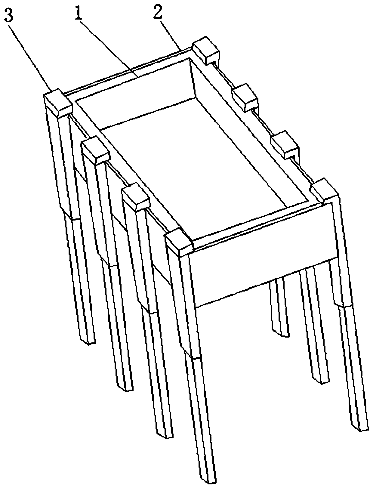
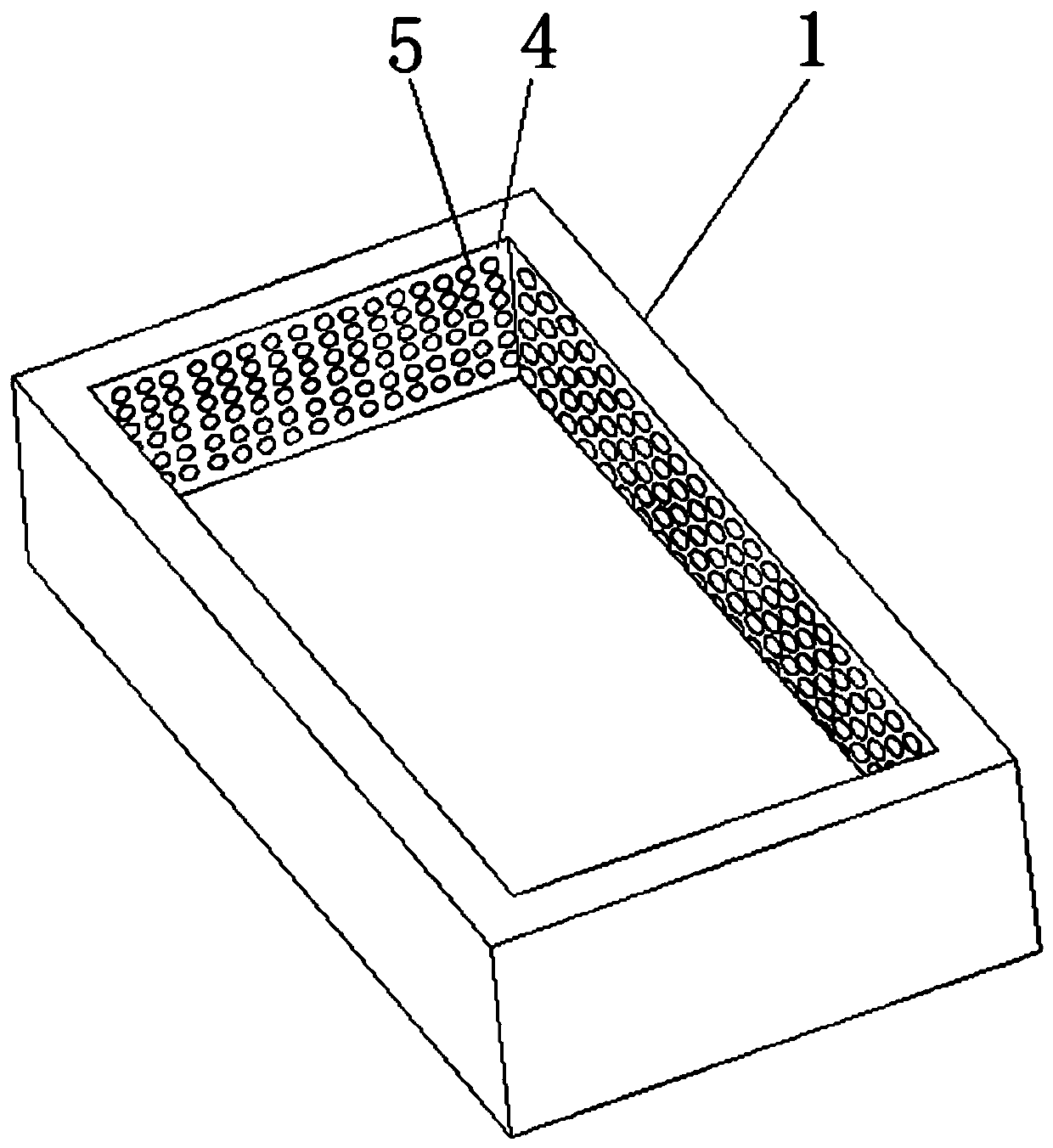

Image

  • Low-power type chip transformer with electromagnetic shielding function
  • Low-power type chip transformer with electromagnetic shielding function
  • Low-power type chip transformer with electromagnetic shielding function

Examples


Embodiment Construction

[0026] The following will clearly and completely describe the technical solutions in the embodiments of the present invention with reference to the accompanying drawings in the embodiments of the present invention. Obviously, the described embodiments are only some, not all, embodiments of the present invention. Based on the embodiments of the present invention, all other embodiments obtained by persons of ordinary skill in the art without making creative efforts belong to the protection scope of the present invention.

[0027] In the description of the present invention, unless otherwise stated, the meaning of "plurality" is two or more; the terms "upper", "lower", "left", "right", "inner", "outer" , "front end", "rear end", "head", "tail", etc. indicate the orientation or positional relationship based on the orientation or positional relationship shown in the drawings, and are only for the convenience of describing the present invention and simplifying the description, rather...


PUM

PropertyMeasurementUnit
thicknessaaaaaaaaaa

Abstract

The invention relates to a low-power type chip transformer with an electromagnetic shielding function. The transformer comprises a resin packaging layer, a first metal grid and a second metal grid. The outer side of the resin packaging layer is provided with a metal powder film. The side of the resin packaging layer is provided with a conductor. The first metal grid is arranged in the resin packaging layer. The first metal grid is arranged in the resin packaging layer, a first round hole is formed in the outer wall of the first metal grid, the second metal grid is arranged in the resin packaging layer, a second round hole is formed in the outer wall of the second metal grid, magnetic particles are arranged on the outer side of the resin packaging layer, and magnetic fibers are arranged onthe outer side of the resin packaging layer. The transformer has the beneficial effects that through respectively using four layers of different composite electromagnetic shielding packaging structures in the transformer packaging layer and the metal powder film, circuit elements are protected, the influence of electromagnetic waves on the external environment is reduced, and the composite electromagnetic shielding packaging structure is suitable for various application occasions with high requirements in different complex environments.

Description

technical field [0001] The invention relates to the technical field of chip transformers, in particular to a low-power chip transformer with electromagnetic shielding. Background technique [0002] At present, low-power chip transformers, such as chip transformers below 100 watts, are widely used in aerospace, military industry, power electronics, biomedical and other fields. Applications in different fields have great impact on the electrical characteristics, compact structure and electromagnetic shielding performance of chip transformers. New requirements have been imposed. Since the previous electromagnetic shielding layer is composed of semiconductor materials, metal materials, insulating materials and other heterogeneous materials, the electromagnetic environment inside the transformer is quite harsh. In addition, due to the external complex electromagnetic environment, it will cause the packaged chip. Electromagnetic interference (EMI), so how to overcome the internal ...

Claims


Application Information

Patent Timeline
Patent Type & Authority Applications(China)
IPC IPC(8): H01F27/36H01F41/00
CPCH01F27/36H01F41/005
Inventor 娄建勇徐铁军钱佳豪徐虹陈志强吴欣
Owner 无锡燊旺和电子科技有限公司
Learn More