Strongly coupled ultra-wideband phased array antenna based on interdigitated resistive surface loading

A phased array antenna and ultra-broadband technology, which is applied to antenna unit combinations with different polarization directions, antennas, antenna arrays, etc., can solve the problems of insufficient working bandwidth, low profile height, and high profile of vertical strong coupling antennas. Achieve the effects of integration and expansion, simple processing, and convenient installation

Active Publication Date: 2021-01-26
UNIV OF ELECTRONICS SCI & TECH OF CHINA
View PDF10 Cites 0 Cited by
  • Summary
  • Abstract
  • Description
  • Claims
  • Application Information

AI Technical Summary

Problems solved by technology

[0004] The purpose of the present invention is to solve the problems of insufficient working bandwidth and high profile of the vertical strong coupling antenna, load an interdigitated resistive surface structure, and add an ultra-wideband feed matching structure to achieve a lower profile height, and has f L -10f L (decade) ultra-wideband coverage and dual-polarized low-profile ultra-wideband strong-coupled dipole phased array antenna with E-plane and H-plane ±60° wide-angle scanning

Method used


Image

  • Strongly coupled ultra-wideband phased array antenna based on interdigitated resistive surface loading
  • Strongly coupled ultra-wideband phased array antenna based on interdigitated resistive surface loading
  • Strongly coupled ultra-wideband phased array antenna based on interdigitated resistive surface loading

Examples


Embodiment Construction

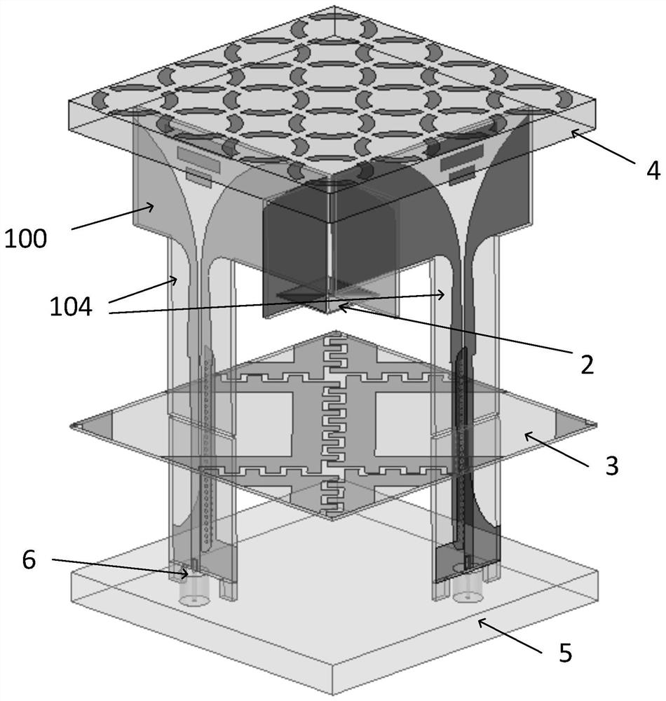
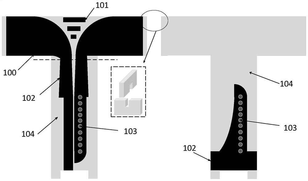
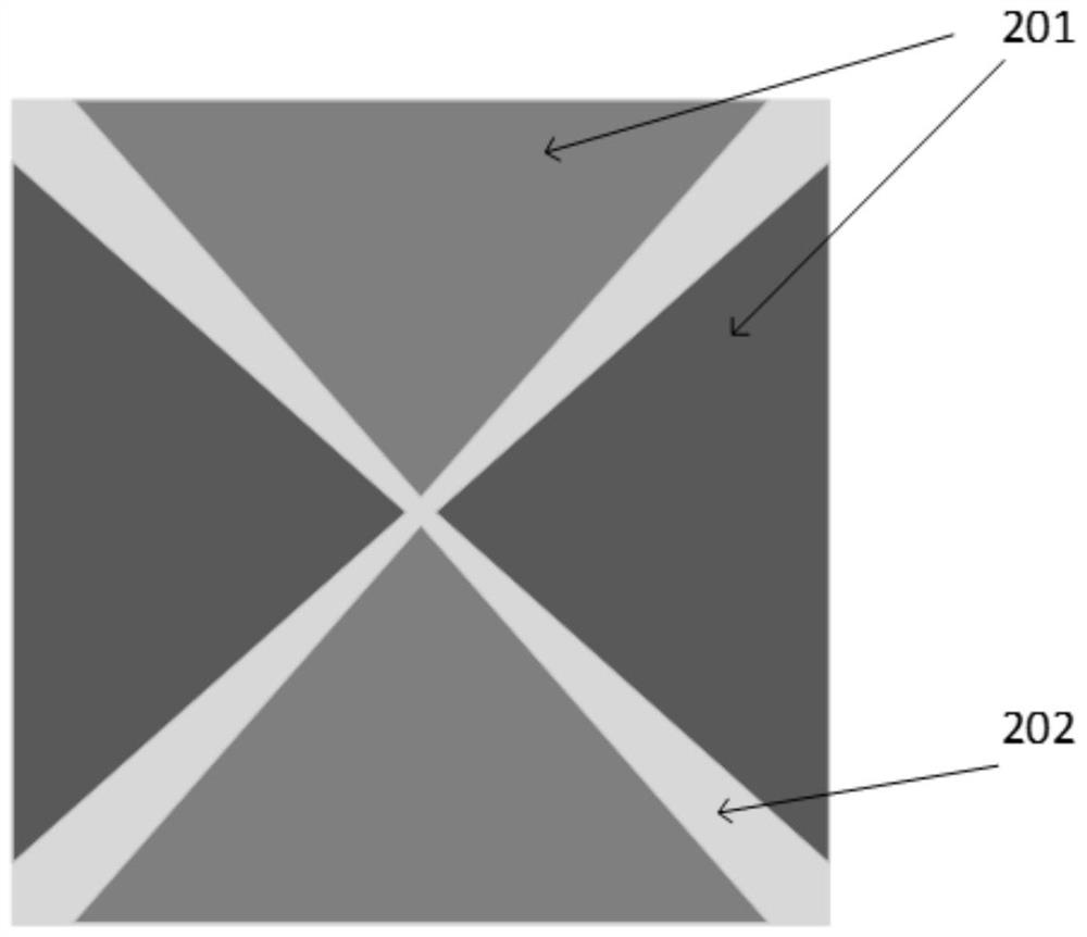
[0023] Such as figure 1 as well as figure 2 As shown, the present embodiment is based on the vertical anti-dipole phased array antenna based on the strong mutual coupling effect. The anti-dipole radiation patch 100 printed on the same antenna dielectric substrate and the ultra-wideband coplanar strip line- Microstrip line feeding balun 102, antenna dielectric substrate 104 in a cross arrangement, parasitic coupling patch 2 close to the intersection of anti-dipole radiation patches of different polarizations, loaded on anti-dipole radiation patches The interdigitated resistive surface 3 between the sheet and the metal floor, the dielectric matching layer 4 perpendicular to the antenna dielectric substrate and arranged on its top, the metal floor 5 perpendicular to the antenna dielectric substrate and arranged on its bottom end, and the coaxial feed Cable 6 constitutes.

[0024] The antenna dielectric substrate 104 is made of FR4 with a dielectric constant of 4.4. It should ...


PUM


Abstract

The invention discloses a strongly coupled ultra-wideband phased array antenna based on interdigitated resistive surface loading and a development method thereof. By improving the traditional vertical strong-coupling phased array antenna, a cross-toed resistive surface is loaded between the antenna and the reflective floor to broaden the working frequency band of the antenna. An ultra-broadband coplanar stripline-microstrip line is used to feed the balun, and the antenna radiation patch is integrated on the same antenna dielectric substrate, which has a simple structure and easy processing. The dielectric matching layer of the metal split ring metamaterial structure printed above the antenna replaces the traditional pure dielectric wide-angle impedance matching layer, which is lighter in weight and thinner in thickness. The structure of the present invention is simple and stable, and is easy to process. L ~10f L In the frequency band, the active standing wave of the 60-degree scanning of the E plane is less than 2.5, and the active standing wave of the 60-degree scanning of the H plane is less than 3.6, and the overall height of the antenna is less than 0.65 high-frequency wavelengths. The phased array antenna designed with this design is especially suitable for the needs Application platform for ultra-wide operating frequency band.

Description

technical field [0001] The invention belongs to the technical field of antenna engineering, in particular to an ultra-wideband phased array antenna based on a strong mutual coupling effect and a development method thereof. Background technique [0002] The phased array antenna technology was proposed by scholars as early as 1925. Its working principle is to control the beam by changing the feed phase in the array antenna. Phased array antennas are widely used in the fields of radar, communication and electronic countermeasures because of their rapid beam changing capabilities, multi-beam scanning capabilities, and space signal power combining capabilities. The development of modern radar, electronic communication and other technologies, as well as the emergence of high-speed platforms such as aircraft and missiles, have put forward higher requirements for the detection range of radar and the ability of fast tracking and identification of targets. In order to meet the large-...

Claims


Application Information

Patent Timeline
Patent Type & Authority Patents(China)
IPC IPC(8): H01Q1/38H01Q1/48H01Q21/00H01Q21/24
CPCH01Q1/38H01Q1/48H01Q21/0075H01Q21/24
Inventor 杨仕文柳俊彦陈益凯屈世伟胡俊
Owner UNIV OF ELECTRONICS SCI & TECH OF CHINA
Why Eureka
Try Eureka