
Vibration deep soil-loosening fertilizer applicator

A fertilizer applicator and subsoiling technology, applied in the field of agricultural machinery, can solve the problems of increasing plow forward resistance, unfavorable water and nutrient absorption, and increased fuel

Pending Publication Date: 2020-07-07
SHENYANG POLYTECHNIC UNIV
View PDF0 Cites 3 Cited by
  • Summary
  • Abstract
  • Description
  • Claims
  • Application Information

AI Technical Summary

Problems solved by technology

The vibrating subsoiling fertilizer applicator in the prior art has a relatively shallow plow layer and forms a thick plow bottom. The existence of the plow bottom makes the crops only grow in the shallow space, and the root system development is limited, which is unfavorable for the absorption of water and nutrients. ; Therefore, in order to make the crops grow better, it is necessary to increase the depth of the plow layer, but the bottom layer of the plow is too thick and solid. After increasing the depth of the plow layer, the subsoiling process needs to consume a lot of energy. The forward resistance of the plow leads to increased fuel consumption and severe wear and tear on tillage parts. Therefore, it is urgent to provide a new vibrating subsoiler fertilizer applicator, which can increase the depth of the tillage layer and reduce energy consumption at the same time.

Method used


Image

  • Vibration deep soil-loosening fertilizer applicator
  • Vibration deep soil-loosening fertilizer applicator
  • Vibration deep soil-loosening fertilizer applicator

Examples


Embodiment 1

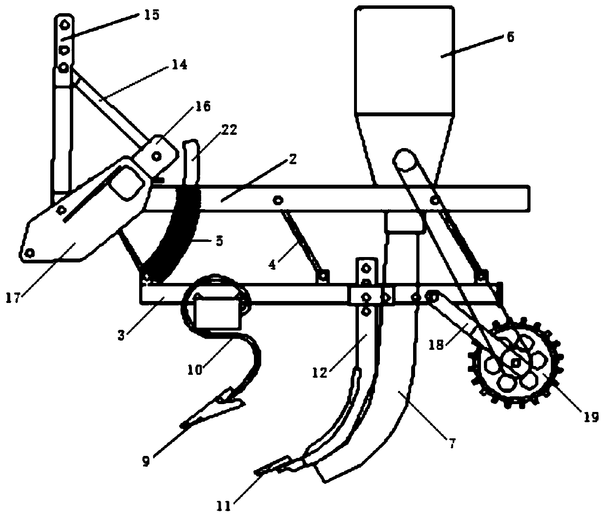
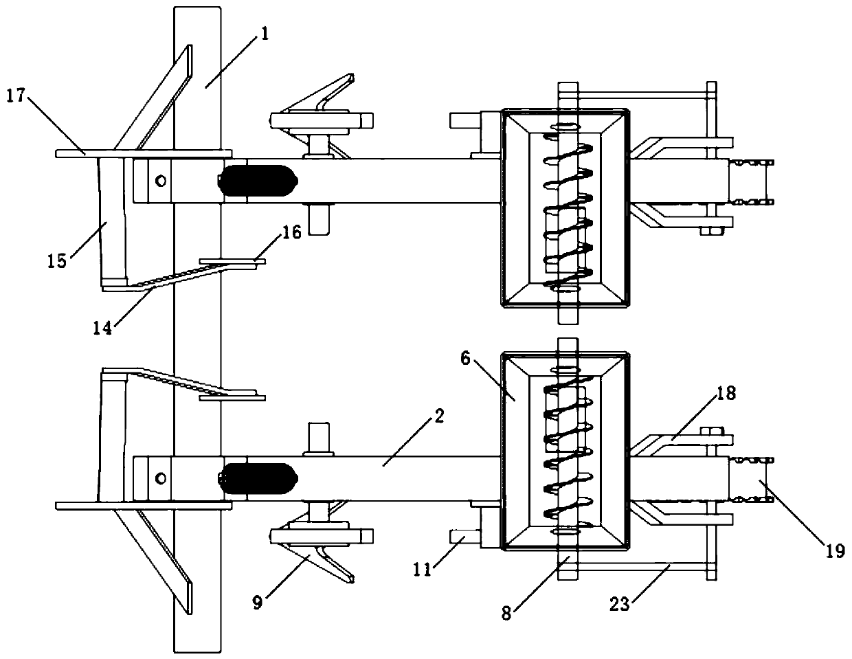
[0069] This embodiment provides a vibrating subsoiling fertilizer applicator, comprising a frame, a spring tooth type subsoiling part for loosening the upper layer of soil is provided at the bottom of the frame, and a spring tooth type subsoiling part is provided with a useful Rigid subsoiling parts for loose substratum soil, elastic teeth subsoiling parts and rigid subsoiling parts are all fixed on the frame, and there is a material deep burying mechanism fixed on the frame behind the rigid subsoiling parts for deep fertilization ;

[0070] Described elastic tooth type subsoiler comprises two-wing shovel 9 and elastic shovel handle 10, and two-wing shovel 9 is fixed on the lower end of elastic shovel handle 10, and elastic shovel handle 10 is fixed on the frame;

[0071] Described material deep burying mechanism comprises material box 6, and material box 6 is fixed on the frame, and the bottom of material box 6 is provided with the auger 8 that is used to control blanking, an...

Embodiment 2

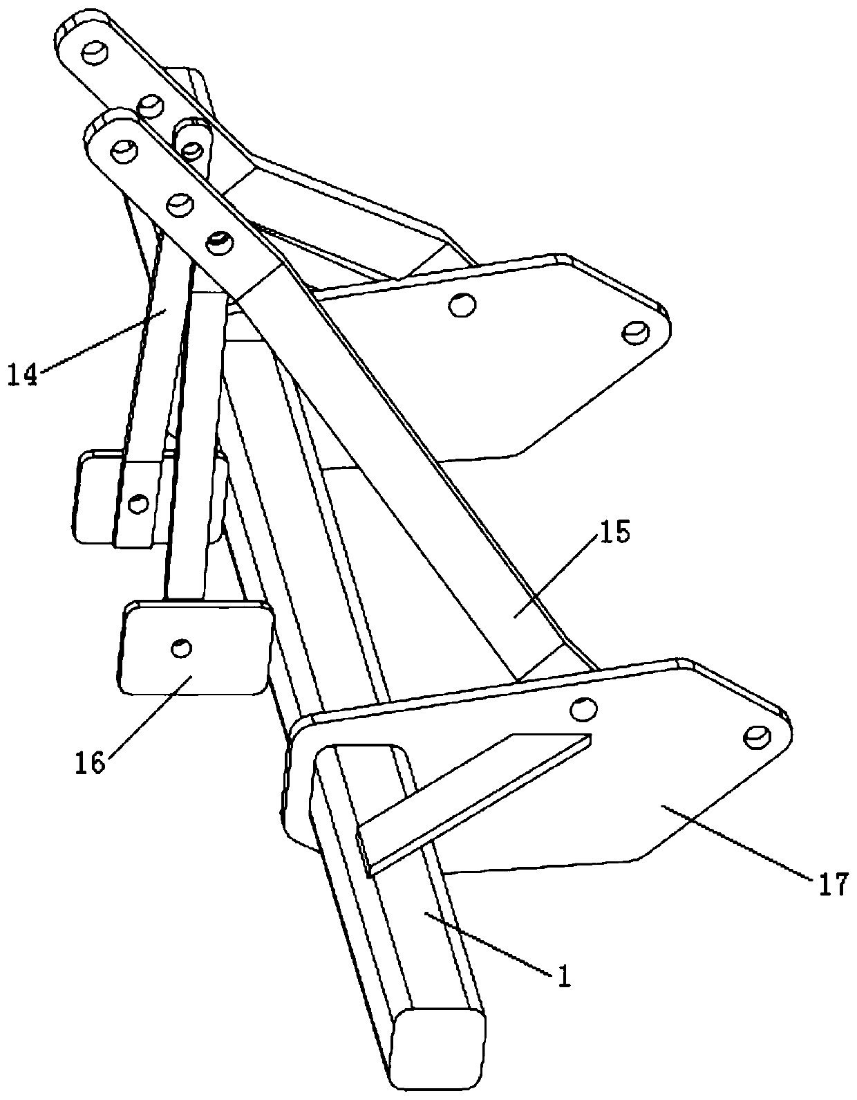
[0081] The present embodiment is based on embodiment 1, and the frame includes a suspension mechanism and a parallel four-bar mechanism; the suspension mechanism is connected with a tractor used to drive the subsoiling fertilizer spreader; the parallel four-bar mechanism includes an upper support beam 2 , the upper support beam 2 is connected with the suspension mechanism, the upper support beam 2 is provided with a lower support beam 3 parallel to it up and down with the terrain, and the upper support beam 2 and the lower support beam 3 are provided with a parallel four bar The pull rod 4 of the mechanism; the spring tooth type subsoiler and the rigid subsoiler are connected as one and fixed on the lower support beam 3; the material box 6 is fixed on the upper support beam 2 .

[0082] Also be provided with spring 5 between described upper support beam 2 and lower support beam 3, spring 5 is sleeved on the spring pull rod 22, the lower end of spring pull rod 22 is hinged with ...

Embodiment 3

[0088] This embodiment is based on Embodiment 1. The double-wing shovel 9 is a triangular double-wing shovel, and the elastic shovel handle 10 is an S-shaped spring-tooth subsoiling shovel handle.

[0089] The elastic shovel handle of this application is an S-shaped spring-tooth subsoiling shovel handle. During the cultivation process, due to the S-shaped characteristics of the elastic shovel handle and the influence of soil resistance and other factors, the elastic shovel handle swings the most and vibrates at the tooth tip. strongest.

[0090] The tillage process of spring-tooth subsoilers can be summarized as follows: the soil resistance increases, causing the deformation of the spring teeth to accumulate energy. When the elastic potential energy of the spring teeth reaches the maximum, the soil yield limit is reached, and the energy is released rapidly to loosen the soil. Therefore, the increase in soil resistance Constant change is the main reason for the vibration of the...


PUM


Abstract

The invention provides a vibration deep soil-loosening fertilizer applicator. The vibration deep soil-loosening fertilizer applicator comprises a frame, wherein the bottom part of the frame is provided with an elastic tooth type deep soil-loosening piece used for loosening upper-layer soil; a rigid deep soil-loosening piece used for loosening lower-layer soil is arranged behind the elastic tooth type deep soil-loosening piece; the elastic tooth type deep soil-loosening piece and the rigid deep soil-loosening piece are connected into a whole and fixedly arranged on the frame; a material deep burying mechanism fixedly arranged on the frame and used for deep fertilization is also arranged behind the rigid deep soil-loosening piece, and comprises a material box which is fixedly arranged on theframe; an auger used for controlling discharging is arranged at the bottom part of the material box; and a discharging pipe is fixedly arranged at the discharging end of the material box, and locatedbehind the rigid deep soil-loosening piece and used for deeply applying a fertilizer into deep loosened soil. According to the vibration deep soil-loosening fertilizer applicator provided by the invention, deep soil-loosening pieces are continuously driven to carry out deep soil loosening on soil by utilizing self-induced vibration factors like negative damping generated by soil cutting of deep soil-loosening pieces during tillage; meanwhile, the fertilizer application work can be completed, so uniform fertilizer addition at a large depth can be realized.

Description

technical field [0001] The invention belongs to the technical field of agricultural machinery, and in particular relates to a vibrating subsoiler fertilizer applicator. Background technique [0002] Deep fertilization refers to the one-time application of formula fertilizer into the soil according to the agronomic requirements to provide nutrients for crops in different periods and meet the nutritional needs of growth and development stages. Soil subsoiling is also called soil subsoiling, which refers to a farming technique that uses tractors to pull subsoiling equipment to loosen the soil to break the bottom layer of the plow, improve the structure of the plow layer, and enhance the ability of soil to resist drought and flood drainage. The vibrating subsoiling fertilizer applicator in the prior art has a relatively shallow plow layer and forms a thick plow bottom. The existence of the plow bottom makes the crops only grow in the shallow space, the root development is limite...

Claims


Application Information

Patent Timeline
IPC IPC(8): A01B49/06A01B35/30A01B35/26A01B35/24A01B35/14A01B35/12A01B51/04A01B59/06A01B63/02
CPCA01B35/12A01B35/14A01B35/24A01B35/26A01B35/30A01B49/065A01B51/04A01B59/06A01B63/02Y02P60/20
Inventor 马星
Owner SHENYANG POLYTECHNIC UNIV
Learn More