High-purity gas preparation device

A high-purity, systematic technology, applied in gas treatment, dispersed particle filtration, membrane, etc.

Active Publication Date: 2020-07-07
CHINA PETROLEUM & CHEM CORP +1
View PDF6 Cites 5 Cited by
  • Summary
  • Abstract
  • Description
  • Claims
  • Application Information

AI Technical Summary

Problems solved by technology

[0004] The above-mentioned patents and the combination technology of high-purity gas production currently used on site are both the comb

Method used


Image

  • High-purity gas preparation device
  • High-purity gas preparation device
  • High-purity gas preparation device

Examples


Embodiment Construction

[0038] The high-purity gas production device of the present invention will be described in detail below. It should be understood that the content described here is only used to illustrate and explain the present invention, but not to limit the present invention.

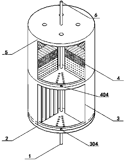
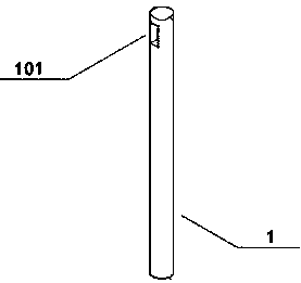
[0039] The high-purity gas production device of the present invention will be further described below in conjunction with the accompanying drawings, as Figure 1 to Figure 6 As shown, the present invention provides a high-purity gas production device, which includes a feed gas inlet pipe 1, a feed gas control distributor 2, a membrane separation module 3, an adsorption separation module 4, a product gas controller 5, and a device center Axis 6.

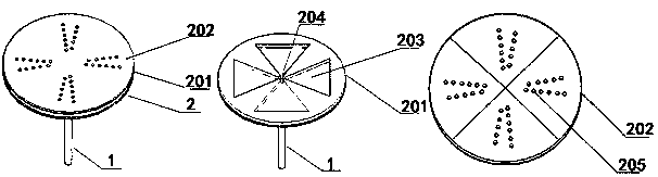
[0040] The raw material gas control distributor 2 includes a raw material gas buffer plate 201 and a raw material gas distribution plate 202 .

[0041] The raw material gas buffer plate 201 is provided with a groove-shaped raw material gas buffer zone 203, and the groove i...


PUM


Abstract

The invention discloses a high-purity gas preparation device. The overall appearance structure of the device is cylindrical or regular polygon-shaped; the device sequentially comprises a feed gas control distributor, a membrane separation module, an adsorption separation module and a product gas controller in the gas flowing direction. By modularly designing the feed gas control distributor, the membrane separation module and the adsorption separation module, the membrane separation and adsorption separation technical equipment are integrated; through the layered design of the feed gas controldistributor and the rotation program control of the gas inlet pipe, the feed gas is sequentially controlled by the membrane separation and adsorption separation module. The device provided by the invention ensures periodic work and regeneration of the membrane separation module and the adsorption separation module, so that respective characteristics and purification functions of a membrane and anadsorbent bed layer are brought into full play.

Description

technical field [0001] The invention relates to the field of gas separation, in particular to a device for producing high-purity gas. Background technique [0002] High-purity gas (generally refers to molar purity greater than 99.9%) can be produced by column separation, membrane separation, adsorption separation and other technologies. In order to obtain high-purity gases, such as hydrogen, methane, oxygen, etc. Column separation generally uses a large amount of liquid phase reflux at the top of the tower or low-temperature absorption liquid to remove impurity gases. In this process, a large amount of liquid phase reflux or cooling of the absorption liquid will consume a lot of energy. Separation to produce high-purity gas has been seldom used; obtaining high-purity gas through membrane separation generally requires two or more stages of purification to be realized. Due to the high cost of the device due to the use of multi-stage membrane separation in series, it is rarely...

Claims


Application Information

Patent Timeline
IPC IPC(8): B01D53/22B01D53/04
CPCB01D53/229B01D53/228B01D53/0407B01D53/0446B01D2259/40086B01D53/22B01D2053/221B01D2259/4145B01D2256/245B01D2256/22B01D2256/16B01D2256/18B01D46/54B01D2053/222B01D2313/10B01D2313/12B01D2313/54B01D2319/04
Inventor 张胜中范得权高明刘震张英
Owner CHINA PETROLEUM & CHEM CORP
Why Eureka
Try Eureka