High-temperature tail gas combustion assisting combustion device of gas turbine

A gas turbine and combustion device technology, applied in the direction of gas fuel burners, burners, combustion methods, etc., can solve problems such as reducing oxygen content and nitrogen oxides NOx, environmental pollution, and reducing the final flue gas emission temperature

Pending Publication Date: 2020-07-07
SHANGHAI LINGYUN RUISHENG COMBUSTION EQUIP CO LTD
View PDF0 Cites 0 Cited by
  • Summary
  • Abstract
  • Description
  • Claims
  • Application Information

AI Technical Summary

Problems solved by technology

[0004] In order to overcome the existing waste heat utilization of gas turbines, due to the lack of combustion-supporting combustion for the exhaust gas after combustion, the heat energy and oxygen content in the high-temperature exhaust gas discharged by the gas turbine are not fully utilized, and the exhaust gas contains a large amount of nitrogen oxides NOx, which will The disadvantages of polluting the environment, the present invention not only can effectively utilize the waste gas discharged from the gas turbine, but also burn natural gas alone to provide heat for the waste heat boiler when the gas turbine stops working, ensuring the normal operation of the boiler, and working together in the relevant mechanisms Under the premise of reducing the exhaust temperature of the final flue gas, reducing the oxygen content and nitrogen oxides NOx in the flue gas, the heat and oxygen of the exhaust gas of the gas turbine can be fully utilized as much as possible, and the high-temperature exhaust combustion of the gas turbine that reduces environmental pollution Burner device

Method used


Image

  • High-temperature tail gas combustion assisting combustion device of gas turbine
  • High-temperature tail gas combustion assisting combustion device of gas turbine
  • High-temperature tail gas combustion assisting combustion device of gas turbine

Examples


Embodiment Construction

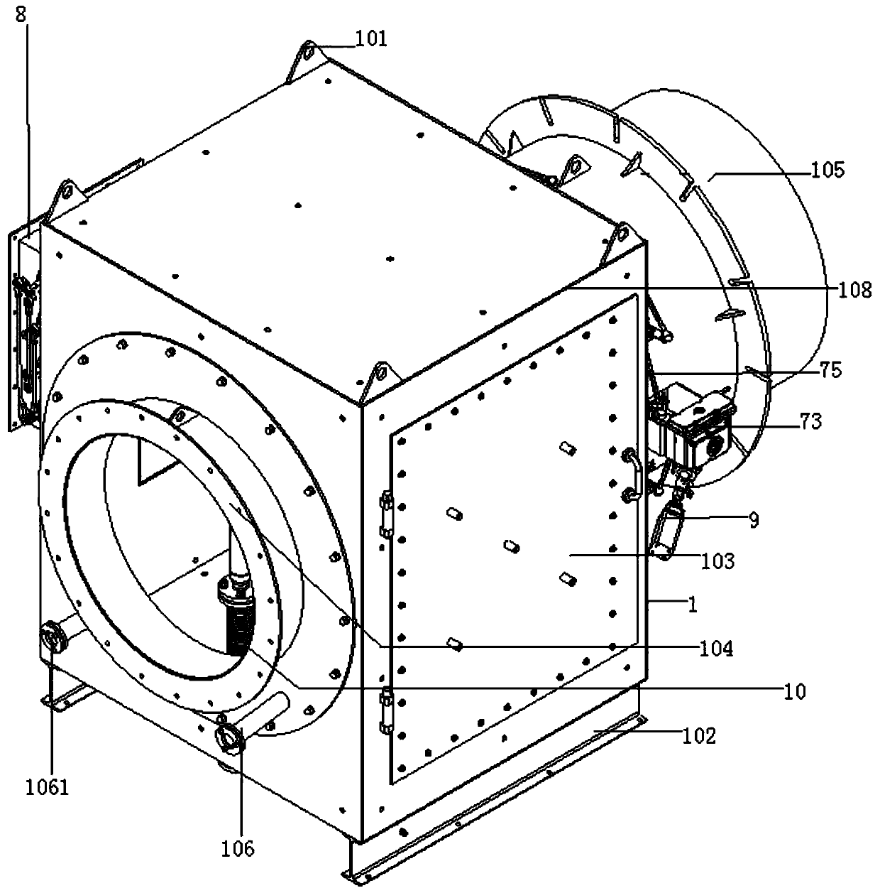
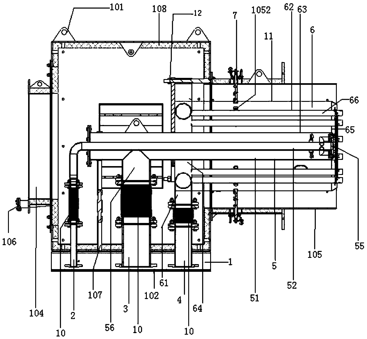
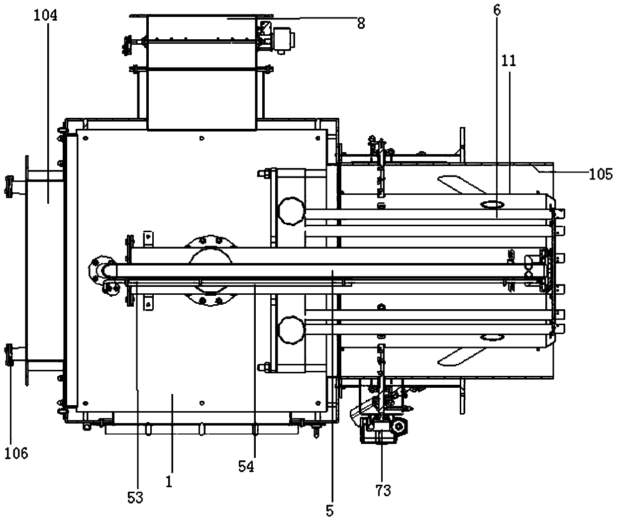
[0022] figure 1 , 2 , 3, 4, 5, 6, 7, 8, and 9, the gas turbine high-temperature tail gas combustion-supporting combustion device includes a hollow rectangular outer shell 1, a central gas pipe 2 with a flange, a central air pipe 3 and the main gas Pipe 4, central gas burner 5, main gas burner 6, high-temperature flue gas diversion mechanism 7, air pipe with electric damper 8, flame detector 9 (using the existing mature flame detector finished product, the main detection center gas combustion 5, the size of the flame produced when the main gas burner 6 burns); there are lifting lugs 101 around the upper end of the housing 1 (to facilitate the overall hoisting of the equipment), and the lower parts of the front and rear ends are transversely welded with support plates 102; The front, rear, left and right sides of 1 are open structures, and a movable inspection door 103 is hingedly installed on the front side of the housing 1 (open the inspection door for inspection when the int...


PUM


Abstract

The invention discloses a high-temperature tail gas combustion assisting combustion device of a gas turbine. The device comprises a shell, a center gas pipe, a center air pipe, a main gas pipe, a center gas combustor, a main gas combustor, a high-temperature smoke flow separation mechanism, an air pipe with an electric air door, and a flame detector; a maintenance door is provided on the front side of the shell; a waste gas connecting pipe is provided on the left side of the shell; the air pipe with the electric air door is mounted at the back side end of the shell; the high-temperature smokeflow separation mechanism is provided at the right side end of the shell; an observation pipe is additionally provided at the left side end of the shell; the center gas pipe, the center air pipe and the main gas pipe are respectively mounted at the lower end of the shell; the center gas combustor is transversely mounted at the middle in the shell; and the main gas combustor is transversely mountedin the middle of the shell, and is concentric with the high-temperature smoke flow separation mechanism after installation. The device can effectively utilize waste gas discharged by the gas turbine,reduces the smoke oxygen content and nitric oxide NOx, and reduces the environment pollution under the precondition that all of heat and oxygen in the tail gas of the gas turbine are utilized.

Description

technical field [0001] The invention relates to the field of gas turbine high-temperature tail gas combustion-supporting burner equipment, in particular to a gas turbine high-temperature tail gas combustion-supporting combustion device. Background technique [0002] When a gas turbine uses natural gas to generate electricity, it will emit high-temperature exhaust gas with a temperature of about 400-500°C. At the same time, because the combustion power generation efficiency of the gas turbine is not high, 15% of the oxygen contained in the combustion exhaust gas is not fully utilized. In order to achieve effective utilization of energy, usually, this part of high-temperature flue gas is directly passed to the waste heat boiler for waste heat utilization. However, when the power of the gas turbine is small, the flow rate of high-temperature exhaust gas is also very limited. The waste heat is also relatively small, and the power of the waste heat boiler that can be driven is ve...

Claims


Application Information

Patent Timeline
Patent Type & Authority Applications(China)
IPC IPC(8): F22B1/18F23D14/26F23D14/46F23G7/06F23J15/06F23L1/00F23L13/00
CPCF22B1/1815F23D14/26F23D14/46F23G7/06F23J15/06F23L1/00F23L13/00
Inventor 陈关海杨高战郝铸平李洁何亚杰金辉孟智炯汤井祝
Owner SHANGHAI LINGYUN RUISHENG COMBUSTION EQUIP CO LTD
Why Eureka
Try Eureka