Supercharge Your Innovation With Domain-Expert AI Agents!

Heat pump for realizing non-halt defrosting by using waste heat of water in cylinder sleeve of internal combustion engine

A cylinder liner water, internal combustion engine technology, applied in the direction of internal combustion piston engine, heat pump, combustion engine, etc., can solve the problems of engine power reduction, gas heat pump waste heat output reduction, gas heat pump power output reduction and other problems

Inactive Publication Date: 2020-07-07
上海南进热能技术有限公司
View PDF5 Cites 4 Cited by
  • Summary
  • Abstract
  • Description
  • Claims
  • Application Information

AI Technical Summary

Problems solved by technology

[0005] In view of the above-mentioned defects of the prior art, the technical problem to be solved by the present invention is that the heat pump system stops heating during the defrosting time, and at the same time the compressor power is reduced, the engine power is reduced, and the waste heat output of the gas heat pump is also reduced accordingly. The power output of the

Method used


Image

  • Heat pump for realizing non-halt defrosting by using waste heat of water in cylinder sleeve of internal combustion engine

Examples


Embodiment 1

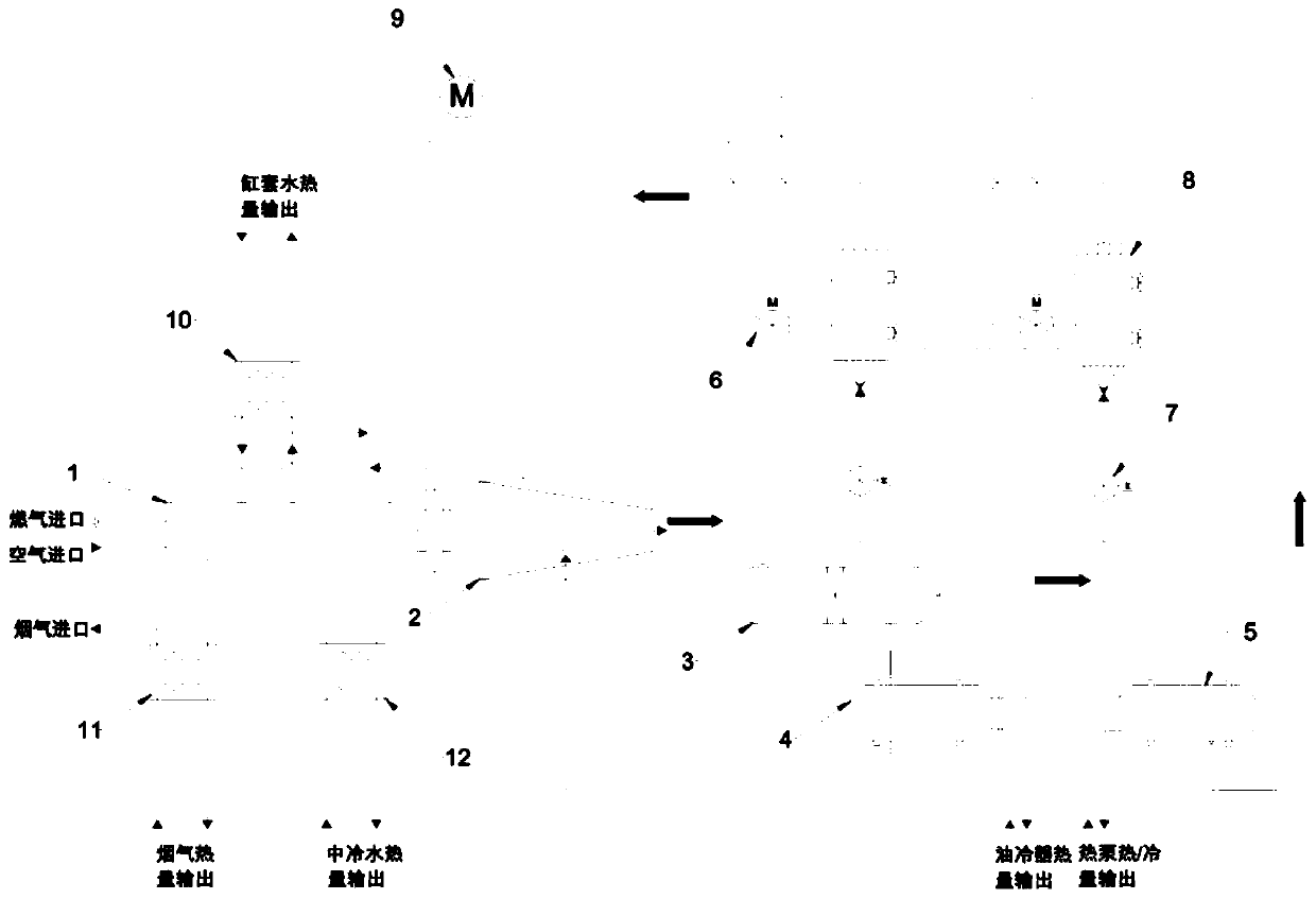
[0051] Such as figure 1 As shown, it is a heat pump for non-stop defrosting of internal combustion engine jacket water waste heat provided by the present invention, driven by natural gas, including gas engine 1, compressor 2, oil separator 3, oil cooler 4, condenser 5, Solenoid valve 6, expansion valve 7, evaporator 8, circulating water pump 9, jacket water heat exchanger 10, flue gas heat exchanger 11, intercooling water heat exchanger 12.

[0052] Among them, the gas engine 1 is used as the driving source; the compressor 2 forms refrigerant gas; the oil component 3 separates lubricating oil and refrigerant; the oil cooler 4 outputs heat to the outside; the condenser 5 forms refrigerant liquid; the solenoid valve 6 is used to start stop bypass; expansion valve 7 is used for throttling control; evaporator 8 performs heat exchange with external air; circulating water pump 9 is used for cylinder jacket water circulation of gas engine; cylinder jacket water heat exchanger 10 is u...

Embodiment 2

[0063] The defrosting operating conditions of the gas heat pump are:

[0064] On the basis of Embodiment 1, when frosting occurs in a certain group of evaporators 8, the corresponding expansion valve 7 is completely closed, the corresponding solenoid valve 6 and the circulating water pump 9 are opened, and the jacket water circulates for heat exchange when it enters the jacket water. Before the evaporator 10, it enters the evaporator 8 that needs defrosting through the circulating water pump 9, and performs defrosting work through the heat of the cylinder jacket water. After the defrosting is completed, close the circulating water pump 9 and the corresponding solenoid valve 6, and open the expansion valve 7 according to the actual situation. Take control and continue the heat pump cycle.


PUM


Abstract

The invention discloses a heat pump for realizing non-halt defrosting by using waste heat of water in a cylinder sleeve of an internal combustion engine, and relates to the field of fuel gas heat pumps. The heat pump comprises a gas engine, a compressor, an oil separator, an oil cooler, a condenser, an electromagnetic valve, an expansion valve, an evaporator, a circulating water pump, a cylinder sleeve water heat exchanger, a flue gas heat exchanger and a medium-cold water heat exchanger. The gas engine is connected with the compressor; the gas engine is connected with the cylinder sleeve water heat exchanger; the gas engine is connected with the flue gas heat exchanger; the gas engine is connected with the medium-cold water heat exchanger; the compressor is connected with oil separator; the compressor is connected with the oil cooler; the compressor is connected with the evaporator; the oil separator is connected with the oil cooler; the oil separator is connected with the condenser;the condenser is connected with the expansion valve; the expansion valve is connected with the evaporator; the evaporator is connected with the electromagnetic valve; the evaporator is connected withthe circulating water pump; and the evaporator is connected with the cylinder sleeve water heat exchanger. The heat pump has multiple purposes of heating domestic water, and improves the utilization rate of primary energy on the premise of gradient multi-aspect application of energy.

Description

technical field [0001] The invention relates to the field of gas heat pumps, in particular to a heat pump which utilizes the waste heat of cylinder jacket water of an internal combustion engine to realize non-stop defrosting. Background technique [0002] Gas heat pump (GHP) is a device that drives a compressor to do work through a gas engine and transfers a low-level heat source to a high-level heat source. It can effectively utilize low-grade heat energy that is difficult to use to achieve energy saving. The heat pump device is mainly equipped with four items: evaporator, condenser, expansion valve and compressor. In addition to the heat generated by the heat pump system itself, the internal combustion engine will also generate a large amount of waste heat during operation. Therefore, the gas heat pump can also generate high-grade heat sources such as flue gas waste heat, cylinder jacket water waste heat, and intercooler water waste heat. These heat sources can be selected...

Claims


Application Information

Patent Timeline
Patent Type & Authority Applications(China)
IPC IPC(8): F25B30/02F25B30/06F25B41/04F25B41/06F25B47/02F25B49/02F02B63/06F02G5/04F25B41/20F25B41/31
CPCF25B30/02F25B30/06F25B47/025F25B49/02F02B63/06F02G5/04F25B2600/2501F25B2600/2513F02G2260/00F25B41/20F25B41/31Y02B30/52Y02T10/12
Inventor 马强刘拴强
Owner 上海南进热能技术有限公司
Features
  • R&D
  • Intellectual Property
  • Life Sciences
  • Materials
  • Tech Scout
  • Unparalleled Data Quality
  • Higher Quality Content
  • 60% Fewer Hallucinations
Learn More