
Device design of high-sensitivity visible-near infrared dual-channel laser fluorescence microscope and imaging method thereof

A technology of fluorescence microscope and imaging method, which is applied in the field of fluorescence microscopy, and can solve the problems of fluorescence molecular quenching, lack of near-infrared fluorescent substance microscopic observation, and distortion of the spatial distribution of fluorescence signals, etc.

Inactive Publication Date: 2020-07-07
NANJING UNIV +1
View PDF5 Cites 3 Cited by
  • Summary
  • Abstract
  • Description
  • Claims
  • Application Information

AI Technical Summary

Problems solved by technology

This type of method has slow imaging speed and large data flow, which requires powerful computer analysis and processing capabilities; the image reconstructed by the analog signal is not a real optical signal, which distorts the spatial distribution of the fluorescent signal; long-term laser excitation may cause fluorescence molecular quenching. destroy or even degrade, changing the information of the sample itself
In addition, the self-made near-infrared fluorescence microscope that can be directly imaged in the laboratory uses LED as the excitation light source. The poor monochromaticity leads to low excitation efficiency. Usually, there are only 1 or 2 fluorescence filters, which leads to insufficient light splitting efficiency of the optical path. The sensitivity and specificity of substance detection are not high
And there is still a lack of powerful equipment for microscopic observation of near-infrared fluorescent substances in China, so it is very necessary to develop a visible-near-infrared dual-channel laser fluorescence microscope

Method used

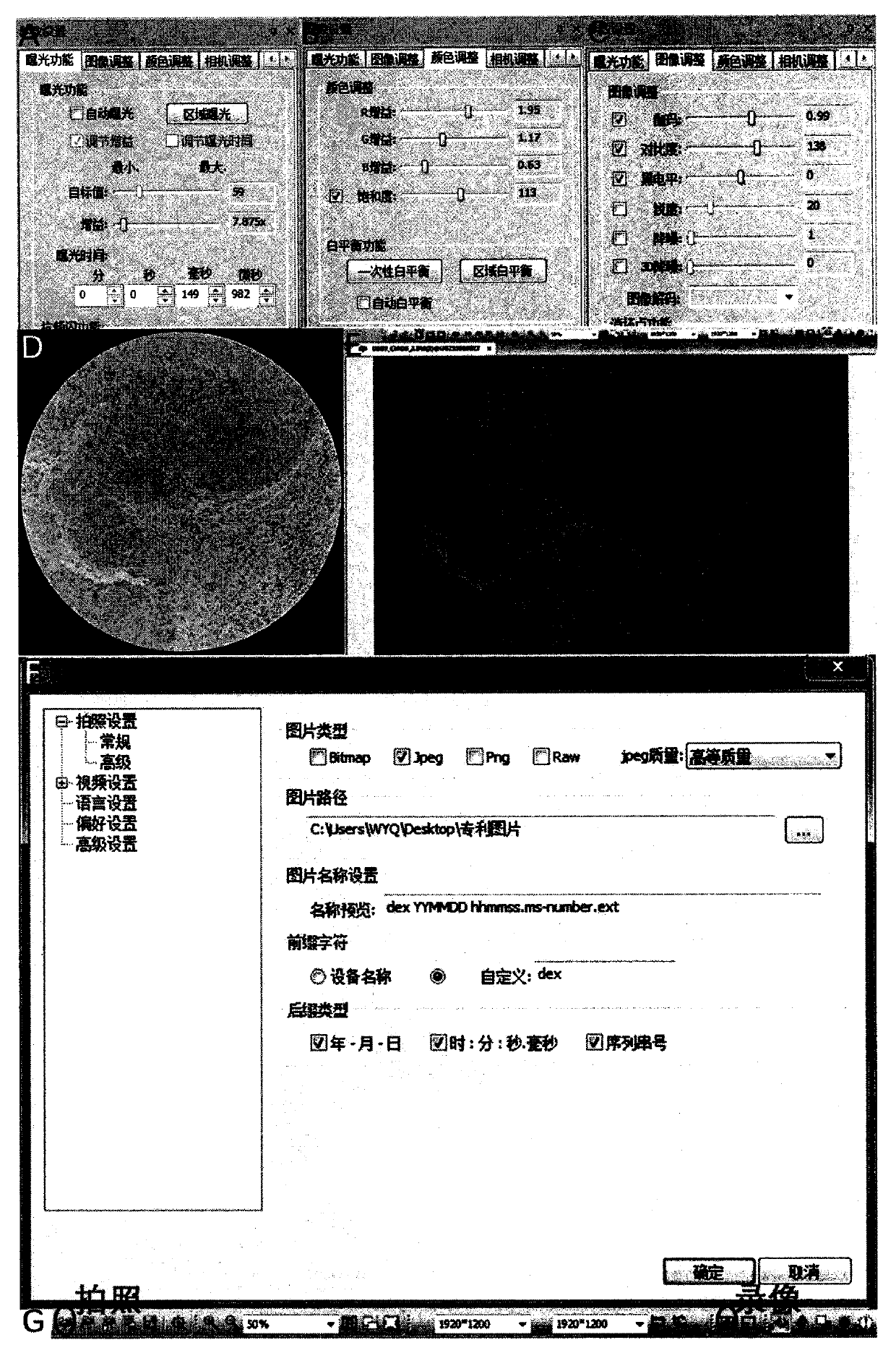
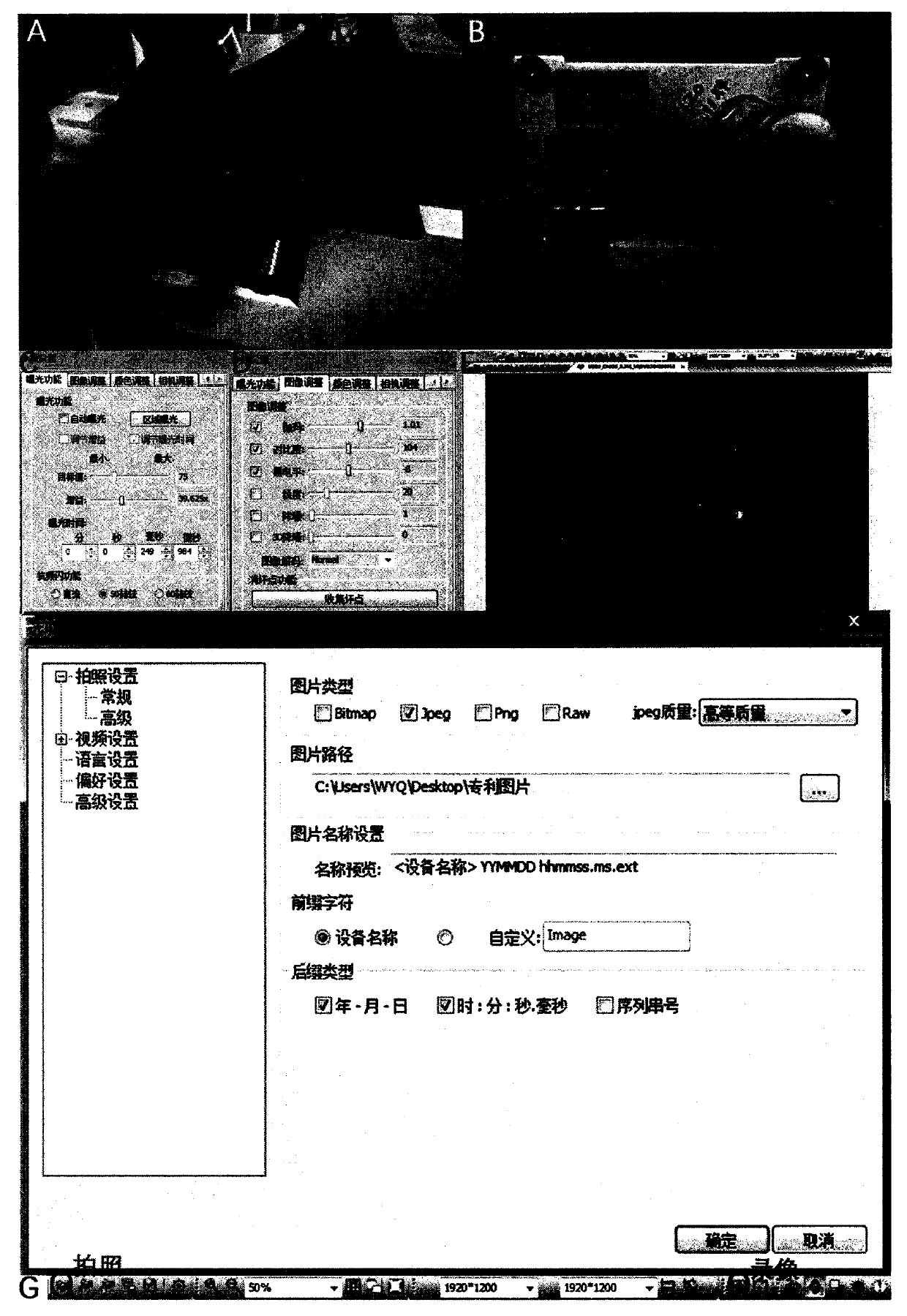

Image

  • Device design of high-sensitivity visible-near infrared dual-channel laser fluorescence microscope and imaging method thereof
  • Device design of high-sensitivity visible-near infrared dual-channel laser fluorescence microscope and imaging method thereof
  • Device design of high-sensitivity visible-near infrared dual-channel laser fluorescence microscope and imaging method thereof

Examples


Embodiment Construction

[0054] The present invention is further clarified in conjunction with the accompanying drawings and specific embodiments.

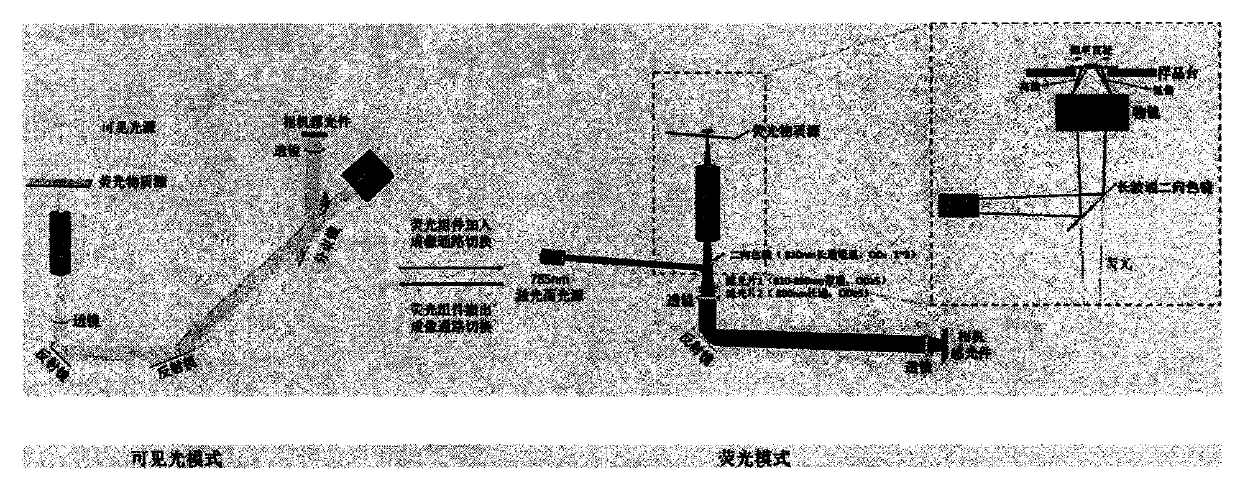
[0055] A device design and imaging method of a highly sensitive visible-near-infrared dual-channel laser fluorescence microscope, including a visible light path working module and a near-infrared light path working module;

[0056] (1) Visible light photography or video recording;

[0057] (2) Near-infrared fluorescence photography or video recording;

[0058] (3) Mechanical calibration and software fine-tuning of dual-channel image overlap;

[0059] (4) Fusion processing of near-infrared and visible light images.

[0060] The visible light pathway work module includes the following parts:

[0061] Such as figure 1 The schematic diagram of the visible light path shown on the left, the visible light source is irradiated on the sample of the fluorescent material source to be tested, and the visible light represented by the yellow beam passes through the...


PUM


Abstract

The invention discloses a device design of a high-sensitivity visible-near infrared dual-channel laser fluorescence microscope and an imaging method thereof. The device comprises a visible light path(A) and a near-infrared light path (B); the imaging method comprises the steps of mechanical calibration, fine adjustment by using Photoshop software and image fusion by using Image-J software. According to the method, visible light and near-infrared fluorescence in the same microscopic region can be observed, and convenient switching is realized. The monochromaticity of the laser is high, and theexcitation energy is gathered along with the increase of the multiplying power; meanwhile, the filtering efficiency of the optical filter combination on background stray light and excitation light ishigh, and the detection sensitivity on fluorescent substances can be improved. According to the invention, visible and near-infrared fluorescence double-channel observation of an ultrathin transparent biological sample is realized, near-infrared fluorescence single-channel observation can be carried out on the surface of an object with any thickness, and an intuitive means is provided for microscopic distribution observation of near-infrared fluorescent substances (especially indocyanine green and derivatives thereof).

Description

technical field [0001] The invention belongs to the field of fluorescence microscopy technology, and in particular relates to a high-sensitivity device design and imaging method for visible-near-infrared dual-channel imaging using laser excitation. Background technique [0002] As an important tool in the current biomedical field, bioluminescent imaging technology can perform real-time and visualized detection of biological components, cells and tissues / organs on a three-dimensional scale. It has been widely used in many fields such as tumor diagnosis, biomolecular detection, drug distribution and metabolism, etc. Fluorescence microscopy imaging technology can detect the structure and composition information of the surface or interior of the sample by detecting the spatial distribution of fluorescent substances in the sample, especially in the microscopic detection of fluorescent labels in biomedicine. The fluorescence detection of most fluorescence microscopes is limited t...

Claims


Application Information

Patent Timeline
IPC IPC(8): G01N21/64G01N21/84G02B21/00G02B21/36
CPCG01N21/6458G01N21/6402G01N21/84G02B21/0052G02B21/008G02B21/367
Inventor 王毅庆王子阳卢乾谢曼曼贺兴臣蔡惠明
Owner NANJING UNIV
Learn More