Synchronous data bus and data transmission system for synchronous control of workpiece table and mask table

A technology of synchronous data and synchronous bus, which is applied in the direction of electrical digital data processing and instruments, can solve the problems of complexity, influence of bus bandwidth, waste of transmission line resources and transmission efficiency, etc., achieve high-precision synchronous motion control, improve transmission speed, simplify The effect of the control step

Active Publication Date: 2021-08-06
SHANGHAI MICRO ELECTRONICS EQUIP (GRP) CO LTD
View PDF6 Cites 0 Cited by
  • Summary
  • Abstract
  • Description
  • Claims
  • Application Information

AI Technical Summary

Problems solved by technology

However, it has the following disadvantages: the transmission order of data packets can only be sent one by one in a fixed manner, and when a certain data packet transmission is blocked, it is impossible to reasonably adjust the transmission order of data packets in real time, that is, when a certain data packet When the transmission is not allowed to be sent by the software handshake, the transmission line will wait for the software handshake signal without transmitting the next data packet
This results in a waste of transmission line resources and low transmission efficiency.
Therefore, the adaptability of this transmission method is poor, and it cannot meet the requirements of large data transmission for the workpiece table (such as 28nm double workpiece table) of the new lithography machine
[0007] In addition, the currently used synchronous data transmission bus 15 such as figure 2 As shown, using address line 10, data line 11, address strobe line 12, data strobe line 13 and handshake signal line 14, a total of 5 communication or control lines, the current position information is input to the original position data receiving card by optical fiber 31, Synchronizing a byte requires 5 steps. The process of transmitting data is too complicated to maximize the use of address and data lines, which affects the bandwidth of bus transmission.

Method used


Image

  • Synchronous data bus and data transmission system for synchronous control of workpiece table and mask table
  • Synchronous data bus and data transmission system for synchronous control of workpiece table and mask table
  • Synchronous data bus and data transmission system for synchronous control of workpiece table and mask table

Examples


Embodiment Construction

[0094] In order to make the purpose and features of the present invention more obvious and understandable, the specific implementation of the present invention will be further described below in conjunction with the accompanying drawings. However, the present invention can be implemented in different forms and should not be limited to the described embodiments. Moreover, in the case of no conflict, the embodiments in the present application and the features in the embodiments are allowed to be combined or replaced with each other. The advantages and features of the present invention will become clearer in conjunction with the following descriptions. It should be noted that all the drawings are in a very simplified form and use imprecise scales, and are only used to facilitate and clearly assist the purpose of illustrating the embodiments of the present invention.

[0095] It should also be stated that the purpose of numbering the steps in the present invention is to facilitate...


PUM


Abstract

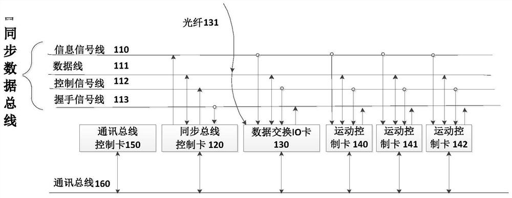
The invention provides a synchronous data bus, which is used for mounting various boards and synchronously transmitting data between boards, including: an information signal line for transmitting address packets, and the address packets include information exchanged between multiple boards The information necessary for the data packet, the information includes at least address information and instruction information; the data line for transmitting the data packet, the storage location of the data packet is specified by the address packet; the control signal line for managing the transmission timing of the data packet; the feedback status of the management board Handshake signal line; synchronous bus control card that controls the timing relationship; after the handshake signal line is valid, the synchronous bus control card broadcasts all address packets sequentially from the information signal line according to the pre-stored address packet priority. Under the control of transmission timing, the data packets pointed to by the address packets are exchanged through the data lines. The invention solves the shortcomings of data blockage and long reading cycle in the existing data transmission system.

Description

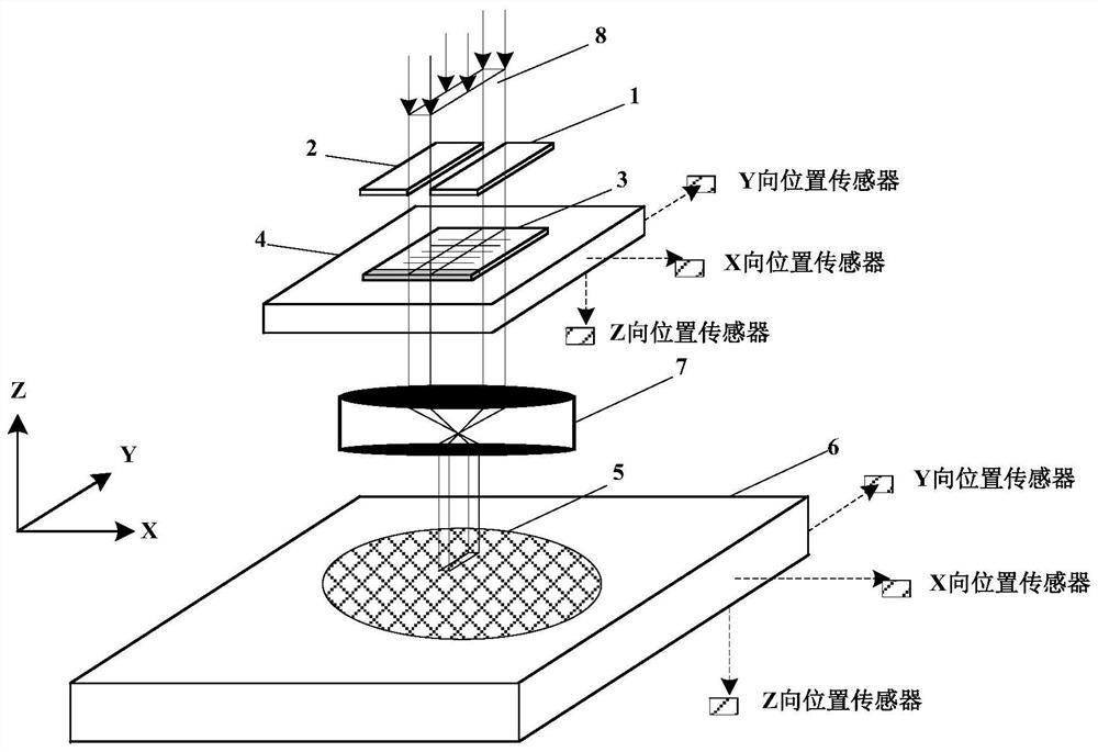
technical field [0001] The invention relates to the technical field of integrated circuit manufacturing equipment, in particular to a synchronous data bus and a data transmission system for synchronous control of a workpiece stage and a mask stage. Background technique [0002] Photolithography is one of the key processes in the process of integrated circuit processing, so the lithography machine is a crucial equipment in the process of integrated circuit processing. [0003] figure 1 Shown is a schematic structural diagram of a workpiece stage and a mask stage of a step-and-scan projection lithography machine. In the figure, the light beam 8 is projected onto the mask 3 after passing through the slit formed by the blade 1 and the blade 2, and the mask 3 passes through the light beam at a set speed at a constant speed. Simultaneously, a substrate such as a silicon wafer 5 is disposed under the lens 7 and moves in a direction opposite to that of the mask 3 . This step-and-...

Claims


Application Information

Patent Timeline
Patent Type & Authority Patents(China)
IPC IPC(8): G06F13/42
CPCG06F13/4286
Inventor 张骥朱晶
Owner SHANGHAI MICRO ELECTRONICS EQUIP (GRP) CO LTD
Why Eureka
Try Eureka