Full-bridge circuit and full-bridge converter

A technology of full-bridge circuit and bridge circuit, which is applied in the direction of adjusting electrical variables, high-efficiency power electronic conversion, instruments, etc., can solve problems such as poor overall efficiency of soft switching.

Pending Publication Date: 2020-07-07
ZTE CORP
View PDF7 Cites 0 Cited by
  • Summary
  • Abstract
  • Description
  • Claims
  • Application Information

AI Technical Summary

Problems solved by technology

[0004] The present invention provides a full-bridge circuit and a full-bridge converter to at least solve

Method used


Image

  • Full-bridge circuit and full-bridge converter
  • Full-bridge circuit and full-bridge converter
  • Full-bridge circuit and full-bridge converter

Examples


Embodiment 1

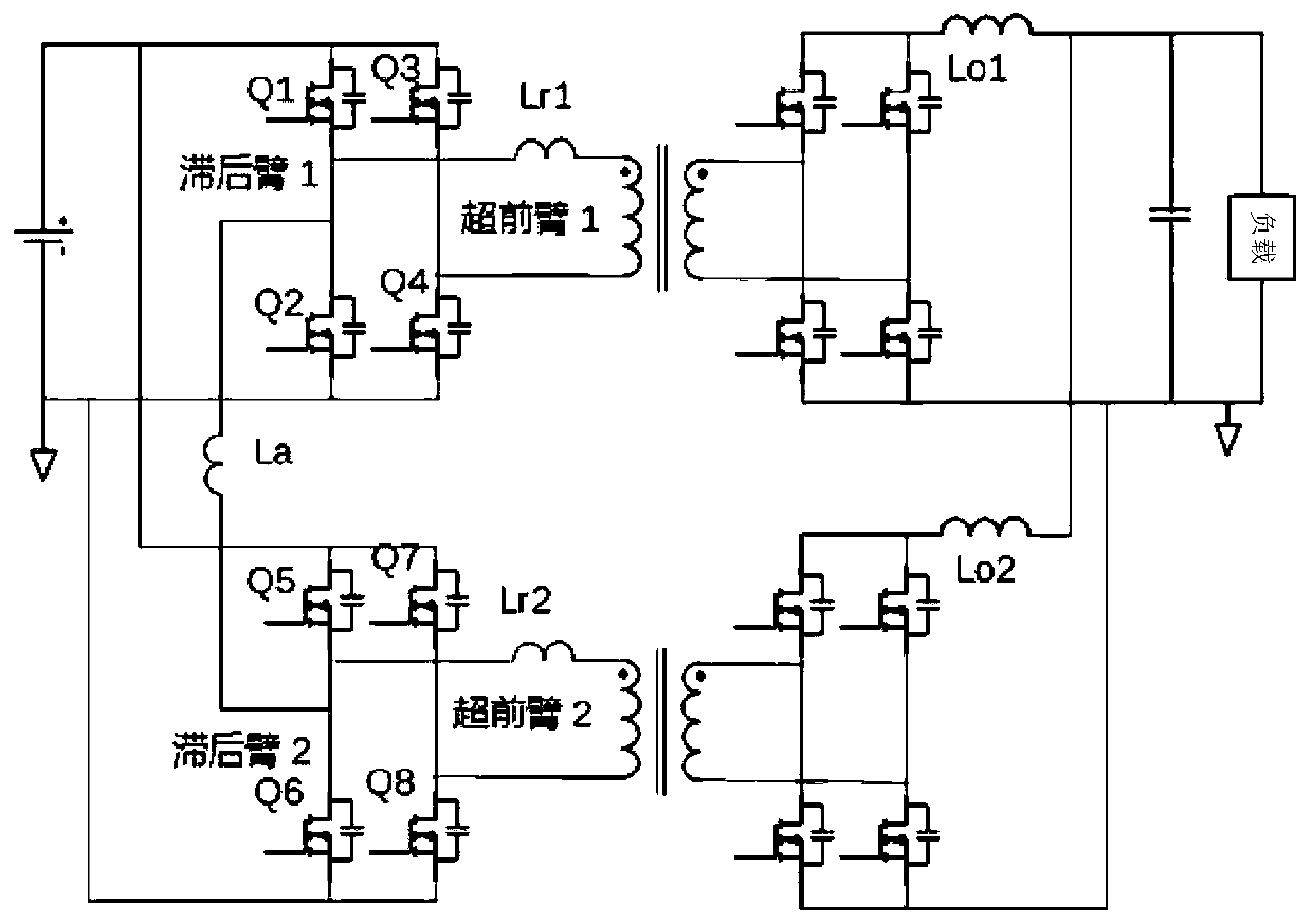
[0033] Such as image 3 As shown, the main circuit of the embodiment of the present invention is a parallel structure of dual-channel full-bridge circuits. Among them, Lr1 and Lr2 are the primary inductances used by the traditional phase-shifting full-bridge circuit to realize soft switching. In actual work, when Q1 and Q2 are turned on, the inductance Lr1 is charged, and the super forearm composed of Q3 and Q4 is turned off. (Q4 is turned off), the current of the inductor Lr1 discharges the output parasitic capacitance of Q3 and Q4, so that the Vds of Q3 is close to 0, and the zero-voltage conduction of Q3 is realized. Since the current of Lr1 is clamped by the output inductor Io during the dead time when the super forearm is turned off, and the output inductance is usually relatively large, the super forearm usually has enough energy to achieve ZVS zero voltage conduction. When the lagging arm composed of Q1 and Q2 is turned off (Q1 is turned off), the current of Lr1 commut...

Embodiment 2

[0038] Such as Figure 6 As shown, the dual-channel full-bridge circuit of Embodiment 2 is in image 3 Based on the improved use of a transformer to achieve, because in the embodiment of the present invention, the phase shift of the two full bridges is controlled by 180 degrees, and the output voltages of the two full bridges are just reversed, so they can be respectively connected to a The two reverse primary side windings of the transformer can be realized by using the same transformer and magnetic core. Meanwhile, in this embodiment, as Figure 6 As shown, the rectification circuit and output inductor on the secondary side can also be simplified into a set of circuits. Therefore, this embodiment is a preferred embodiment of a power supply with high efficiency and high power density. It should be noted that, in this embodiment, other control methods and processes are the same as those in Embodiment 1 above, and will not be repeated here.

Embodiment 3

[0040] Such as Figure 7 As shown, the difference from the above-mentioned embodiments is that in this embodiment 3, the secondary side of the transformer adopts a double-winding synchronous rectification circuit, compared with Figure 6 In the shown embodiment 2, the synchronous rectification of the secondary side of this embodiment can be realized by two switching tubes, therefore, the number of components can be further simplified and the cost can be reduced in certain application occasions. It should be noted that, in this embodiment, other control methods and processes are the same as those in the above embodiment, and will not be repeated here.


PUM


Abstract

The invention provides a full-bridge circuit and a full-bridge converter. The full-bridge circuit comprises a primary side bridge circuit, a transformer and a secondary side rectifying circuit, the primary side bridge circuit comprises a first primary side bridge circuit and a second primary side bridge circuit which are connected in parallel, and an auxiliary inductor is connected between a lagging arm of the first primary side bridge circuit and a lagging arm of the second primary side bridge circuit. According to the invention, the auxiliary inductor of which the current is not influenced by the load is connected between the two full-bridge circuits connected in parallel, so that soft switching of the lag arm can be realized under the condition of smaller inductance, and the current reversing speed is increased by reducing the inductance so as to solve the problem of duty ratio loss.

Description

technical field [0001] The invention relates to the field of electronic circuits, in particular to a full-bridge circuit and a full-bridge converter. Background technique [0002] Switching power supply is the most widely used in the current electronic field because of its volume advantage brought by high frequency and high conversion efficiency brought about by only working in the switch state. With the continuous improvement of equipment power requirements, the requirements for power density and efficiency of switching power supplies are also continuously increasing. In traditional switching power supplies, switching loss has become the main factor preventing further increase of switching frequency to reduce volume. Switching loss is caused by the switching device simultaneously bearing voltage and current, as well as the energy loss of charging and discharging on parasitic capacitance during the switching process. Therefore, in the prior art, soft switching of a phase-s...

Claims


Application Information

Patent Timeline
IPC IPC(8): H02M3/335
CPCH02M3/3353H02M1/0058Y02B70/10H02M3/285H02M3/33573H02M3/33584H02M1/0043H02M7/493
Inventor 王林国朱俊杰
Owner ZTE CORP
Why Eureka
Try Eureka