Check patentability & draft patents in minutes with Patsnap Eureka AI!

Dry desulfurization system and dry desulfurization method

A dry desulfurization and process system technology, applied in chemical instruments and methods, combustion methods, separation methods, etc., can solve problems such as equipment damage, high absorbent consumption, and affecting the stability of the circulating fluidized bed dry desulfurization system , to achieve the effects of improving stability, reducing the difficulty of desulfurization, saving investment and operation and maintenance costs

Pending Publication Date: 2020-07-10
FUJIAN LONGKING DSDN ENGINEERING CO LTD
View PDF0 Cites 0 Cited by
  • Summary
  • Abstract
  • Description
  • Claims
  • Application Information

AI Technical Summary

Problems solved by technology

Although the circulating fluidized bed dry desulfurization process has many advantages, but in the treatment of high concentration SO 2 For flue gas, the absorbent consumption of circulating fluidized bed dry desulfurization process is relatively large
Secondly, high-temperature flue gas above 260°C is likely to affect the stability of the CFB dry desulfurization system, and it is easy to cause equipment damage such as bag burning or sticking bags in the CFB dry desulfurization system

Method used


Image

  • Dry desulfurization system and dry desulfurization method
  • Dry desulfurization system and dry desulfurization method

Examples


no. 1 Embodiment

[0044] The first specific embodiment of the present invention provides a dry desulfurization system and a dry desulfurization method, which are suitable for the dry desulfurization process of Claus tail gas coupled with coal-fired boiler flue gas.

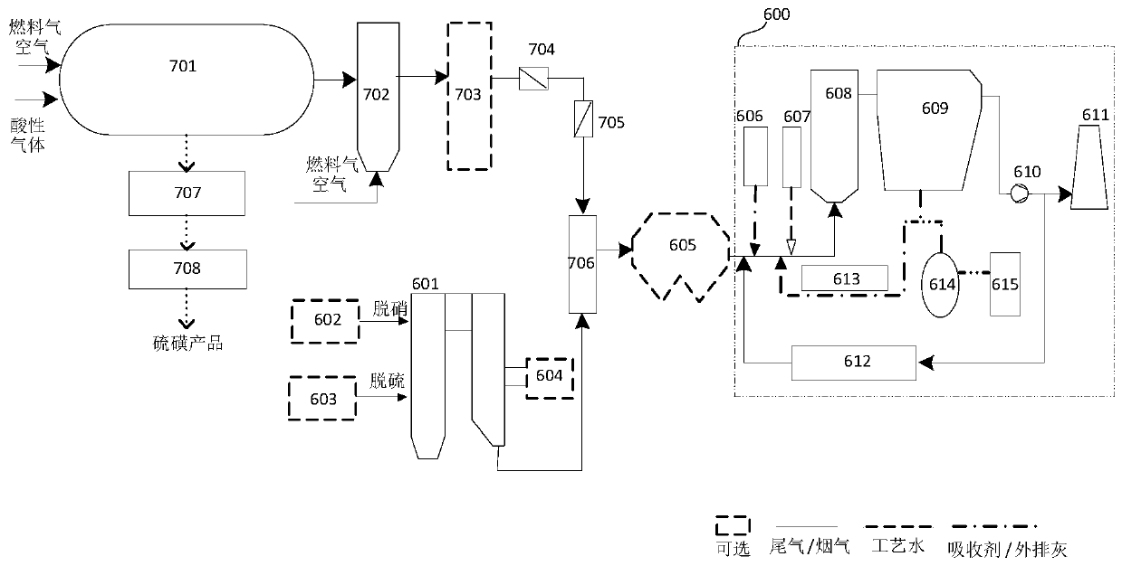
[0045] see figure 1 , figure 1 A structural schematic diagram of a dry desulfurization system suitable for Claus tail gas coupled with coal-fired boiler flue gas provided by the first specific embodiment of the present invention.

[0046] The dry desulfurization system includes a coal-fired boiler 601, a flue gas mixer 706, a flue gas circulating fluidized bed device 600 (ie, a flue gas circulating fluidized bed dry desulfurization device) and a Claus process system. in:

[0047] The Claus process system includes a Claus reactor 701, an incinerator 702, an electric windshield 704, a manual windshield 705, a liquid sulfur storage 707, and a sulfur granulator 708. It is also possible to choose whether to install a waste heat utiliz...

no. 2 Embodiment

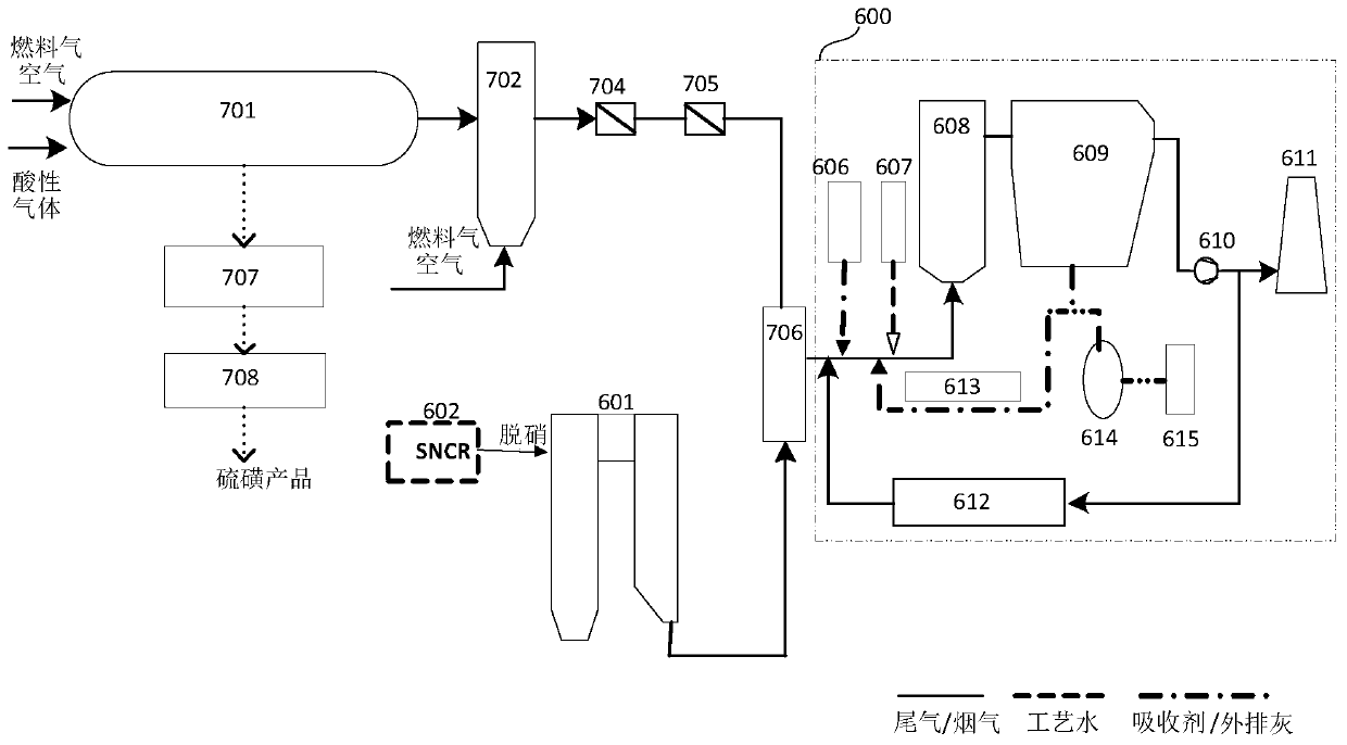
[0071] The second specific embodiment of the present invention provides a dry desulfurization system and a dry desulfurization method, which are suitable for the dry desulfurization process of Claus tail gas coupled with coal-fired boiler flue gas. Please refer to the dry desulfurization system figure 2 , figure 2 A schematic structural diagram of a dry desulfurization system suitable for Claus tail gas coupled with coal-fired boiler flue gas is provided for the second specific embodiment of the present invention; the dry desulfurization method can refer to the above-mentioned first specific embodiment.

[0072] The second specific embodiment of the present invention provides that the dry desulfurization system is a transformation project, see below for details.

[0073] The Claus tail gas desulfurization device in a coal chemical enterprise, its Claus process flow is the traditional two-stage Claus process + SCOT (hydrogenation reduction + MDEA selective absorption) + inci...


PUM


Abstract

The invention discloses a dry desulfurization system and a dry desulfurization method, and is suitable for the dry desulfurization process of Claus tail gas coupled coal-fired boiler flue gas. The drydesulfurization system comprises a coal-fired boiler, a flue gas mixer, a flue gas circulating fluidized bed device and a Claus process system. The flue gas output pipeline of the coal-fired boiler is connected with the flue gas mixer, the tail gas output pipeline of the Claus process system is connected with the flue gas mixer, and the flue gas mixer is used for mixing Claus tail gas with flue gas of the coal-fired boiler and inputting mixed flue gas into the flue gas circulating fluidized bed device for desulfurization treatment. The Claus tail gas can meet the higher requirements of the ultralow emission standard of the flue gas of the coal-fired boiler with lower investment and operation cost.

Description

technical field [0001] The invention relates to the technical field of chemical industry, in particular to a dry desulfurization system and a dry desulfurization method, which are suitable for the dry desulfurization process of Claus tail gas coupled with coal-fired boiler flue gas. Background technique [0002] In recent years, the field of coal chemical industry has ushered in a period of rapid development. The by-products in the coal liquefaction process contain a certain concentration of H 2 If acid gases such as S are discharged directly, on the one hand, the direct discharge of acid gases will cause a lot of waste of sulfur resources, and on the other hand, it will cause serious air pollution. [0003] The Claus method is a relatively mature and widely used H 2 Acid gas treatment process in which S is converted to sulfur, during the conversion process will form H 2 S, SO 2 Sulfur recovery tail gas with the same composition, the tail gas temperature is usually 250 ℃ ...

Claims


Application Information

Patent Timeline
IPC IPC(8): B01D53/75B01D53/56B01D50/00B01D53/80B01D53/86C01B17/04F23G7/06
CPCB01D50/00B01D53/56B01D53/75B01D53/80B01D53/8625B01D2258/0283C01B17/0404F23G7/06F23G2209/14Y02P20/129
Inventor 钟林发詹威全郭志航陈树发林春源林福林连娥桂刘碧莲张原王建春
Owner FUJIAN LONGKING DSDN ENGINEERING CO LTD
Features
  • R&D
  • Intellectual Property
  • Life Sciences
  • Materials
  • Tech Scout
  • Unparalleled Data Quality
  • Higher Quality Content
  • 60% Fewer Hallucinations
Learn More