Dust collection equipment for textile printing and dyeing and dust collection method of dust collection equipment

A technology for textile printing and dyeing and equipment, which is applied in the field of vacuuming equipment for textile printing and dyeing and its dust collection, can solve the problems of dust and organic gas leakage, damage to the lungs of surrounding workers, and dust and organic gas cannot be completely pumped upwards. Achieve the effect of reducing power loss and protecting the cyclone separator

Pending Publication Date: 2020-07-10
李新云
View PDF0 Cites 0 Cited by
  • Summary
  • Abstract
  • Description
  • Claims
  • Application Information

AI Technical Summary

Problems solved by technology

But this vacuum equipment still has the following defects: 1. The vertical height of the printing and dyeing station from the fan A (9) is long, causing the suction force at the lower port of the straight cylinder to be small, so that the dust and organic gas cannot be completely upwardly drawn. Go away, that is, part of the dust and organic waste gas stays in the lower port of the straight tube (13) and cannot be sucked up, which has the defect of poor dust suction effect
2. A large amount of dust is generated during the printing and dyeing process, so the cyclone separator (8) needs to consume a lot of power to complete the separation of dust and organic gas
3. There is a gap between the woven cloth (40) and the lower end surface of the straight cylinder (13), and the generated dust and organic gas are easy to leak from the gap, which not only reduces the dust collection effect of the fan, but also damages the lungs of the surrounding workers after leakage
4. Although the chemical agent sprayed from the spray system in the absorption tower can absorb the organic gas, but the flow rate of the chemical agent is too fast and the contact area is small, it takes a long time to completely absorb the organic gas, thus reducing the organic gas Processing efficiency

Method used


Image

  • Dust collection equipment for textile printing and dyeing and dust collection method of dust collection equipment
  • Dust collection equipment for textile printing and dyeing and dust collection method of dust collection equipment
  • Dust collection equipment for textile printing and dyeing and dust collection method of dust collection equipment

Examples


Embodiment 1

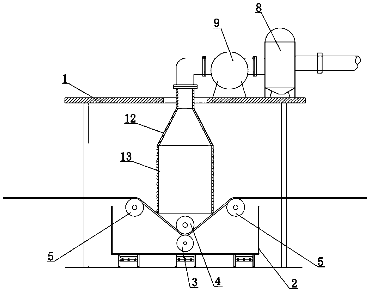
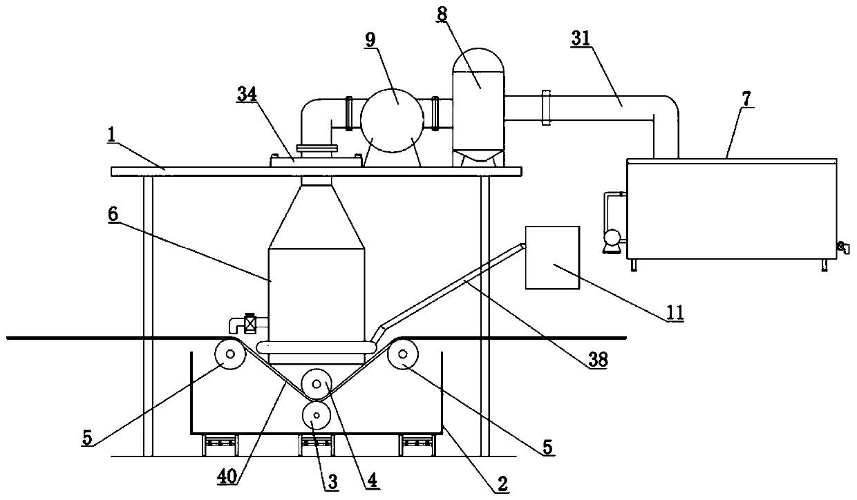
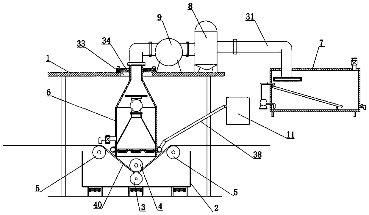
[0040] Embodiment one: if Figure 2-9 As shown, a kind of vacuuming equipment for textile printing and dyeing, which includes a gantry 1, a printing and dyeing box 2 arranged under the beam of the gantry 1, and a pressure wheel 3 and a printing and dyeing wheel 4 are installed in the printing and dyeing box 2, and the printing and dyeing wheel 4 Located directly above the pressing wheel 3, the printing and dyeing wheel 4 is tangent to the pressing wheel 3. The printing and dyeing box 2 is also rotatably installed with guide wheels 5 located on the left and right sides of the printing and dyeing wheel 4. It is characterized in that it also includes a dust collection device 6, organic gas The absorption device 7, the cyclone separator 8 and the fan A9 fixed on the top of the crossbeam, the dust suction device 6 includes a dust suction tube, an annular pipe 10 and an air compressor 11, and the dust suction tube is arranged at the lateral bottom of the gantry frame 1, and the sucti...

Embodiment 2

[0050] Embodiment two: if Figure 10 As shown, a kind of vacuuming equipment for textile printing and dyeing, the difference between this embodiment and the second embodiment is that it also includes a controller 39, and the controller 39 is arranged on the column of the gantry 1, and the controller 39 It is electrically connected with stop valve 37, liquid outlet valve 29, replenishment valve 35, fan A9, exhaust fan 17, and fan B18. It can control the start or stop of fan A9, exhaust fan 17 and fan B18, which facilitates the operation of the work and has the characteristics of high degree of automation.


PUM


Abstract

The invention discloses dust collection equipment for textile printing and dyeing. The dust collection equipment comprises a dust collection device, an organic gas absorption device, a cyclone separator and a fan A, and the cyclone separator and the fan A are fixedly arranged at the top of a cross beam; the dust collection device comprises a dust collection cylinder, an annular pipe and an air compressor; and the dust collection cylinder is arranged below the cross beam of a portal frame, a conical cylinder is fixedly arranged at the top of a straight cylinder, a small port of the conical cylinder upwards penetrates through the cross beam and is connected with an air inlet of the fan A through a pipe clamp, the straight cylinder is positioned right above a printing and dyeing wheel, an inner conical cylinder and a partition plate are welded in the straight cylinder, the partition plate is positioned below the inner conical cylinder, an exhaust fan is fixedly arranged on the bottom surface of each mounting hole, a fan B is connected to the small port of the inner conical cylinder through a pipe clamp, and a disc positioned in the conical cylinder is fixedly arranged at an air outletof the fan B. The dust collection equipment for textile printing and dyeing has the beneficial effects that the structure is compact, the dust collection effect is good, power loss of the cyclone separator is reduced and the organic gas absorption efficiency is improved.

Description

technical field [0001] The invention relates to the technical field of dust suction and dust removal in textile printing and dyeing production, in particular to a dust suction device and a dust suction method for textile printing and dyeing. Background technique [0002] The original meaning of textile is taken from the general term of spinning and weaving, but with the continuous development and improvement of the textile knowledge system and subject system, especially after the emergence of non-woven textile materials and three-dimensional composite weaving technologies, the current textile is not only a traditional Hand spinning and weaving also include garment, industrial and decorative textiles produced by non-woven technology, modern three-dimensional weaving technology, and modern electrostatic nano-netting technology. Therefore, modern textile refers to a multi-scale structure processing technology of fibers or fiber aggregates. Ancient Chinese textile and printing a...

Claims


Application Information

Patent Timeline
IPC IPC(8): D06B1/14D06B23/20B01D45/16B01D53/14
CPCB01D45/16B01D53/1487D06B1/14D06B23/20
Inventor 李新云
Owner 李新云
Why Eureka
Try Eureka