Electrodeless ultraviolet sterilization lamp for ventilation pipeline

A ventilation duct, extreme ultraviolet technology, applied in the direction of space heating and ventilation, heating mode, lighting and heating equipment, etc., can solve the problems of small light decay, long lamp life, small ultraviolet radiation, etc. The effect of long lamp life and easy surface cleaning

Pending Publication Date: 2020-07-10
上海暄恩光电科技有限公司
View PDF0 Cites 0 Cited by
  • Summary
  • Abstract
  • Description
  • Claims
  • Application Information

AI Technical Summary

Problems solved by technology

[0005] For this reason, the embodiment of the present invention provides an electrodeless ultraviolet sterilizing lamp for ventilation ducts. Through the design of the auxiliary mechanism, due to the use of a high-power electrodeless ultraviolet sterilizing lamp illuminant, the lamp tube has a long service life, low light decay, and high-efficiency sterilization. The protection range exceeds 1 meter, and the effective life is as high as 60,000 hours. At the same time, it can instantly eliminate bacteria and viruses in the airflow through the ventilation duct. The connecting frame with the main slide rail and the secondary slide rail is installed to facilitate the surface cleaning of the quartz lamp. Long-term stable sterilization effects can be achieved without replacing the entire lamp. At the same time, the invention is widely used in various occasions such as hospitals, office buildings, shopping malls, hotels, and families. It can produce sterile and fresh air for ventilation ducts to solve existing problems. Ultraviolet lamps in the technology all have the characteristics of low power, low ultraviolet radiation and short life.

Method used


Image

  • Electrodeless ultraviolet sterilization lamp for ventilation pipeline
  • Electrodeless ultraviolet sterilization lamp for ventilation pipeline
  • Electrodeless ultraviolet sterilization lamp for ventilation pipeline

Examples


Embodiment Construction

[0025] The implementation mode of the present invention is illustrated by specific specific examples below, and those who are familiar with this technology can easily understand other advantages and effects of the present invention from the contents disclosed in this description. Obviously, the described embodiments are a part of the present invention. , but not all examples. Based on the embodiments of the present invention, all other embodiments obtained by persons of ordinary skill in the art without making creative efforts belong to the protection scope of the present invention.

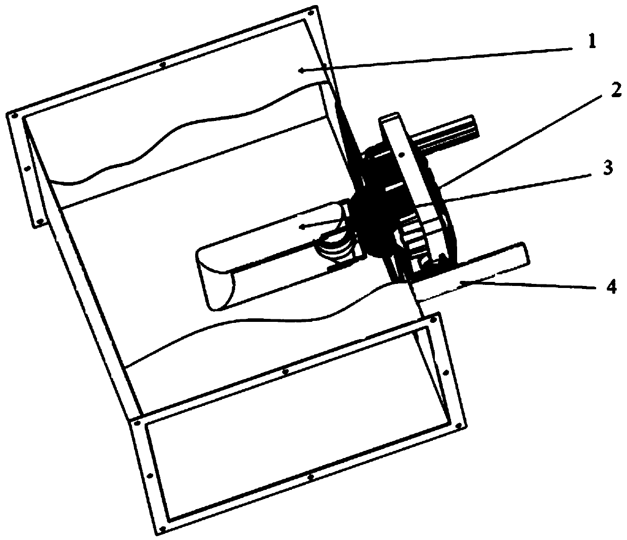
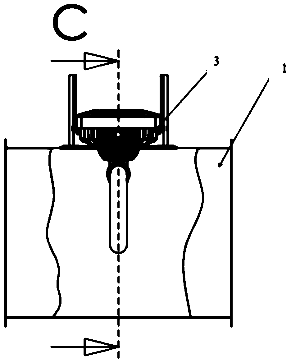
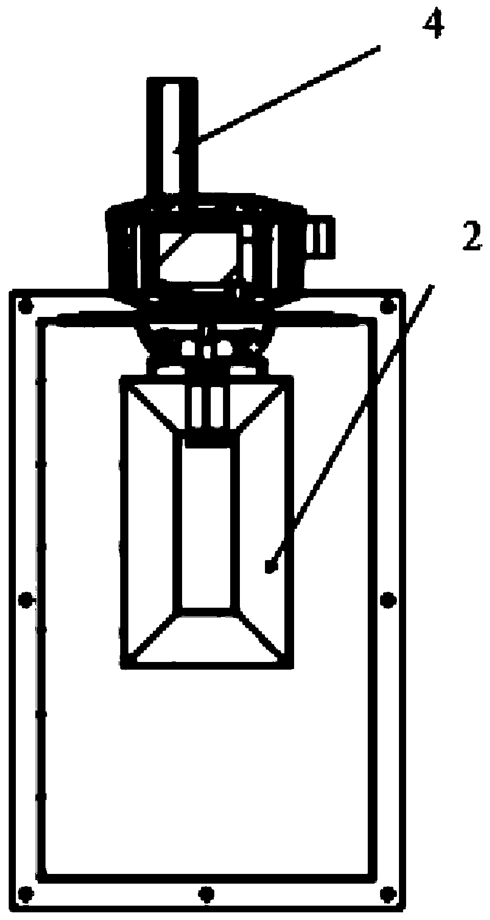
[0026] Refer to the attached Figure 1-6 , a ventilation duct electrodeless ultraviolet sterilizing lamp of this embodiment, comprising a ventilation duct 1, an auxiliary mechanism is provided on the ventilation duct 1, and the auxiliary mechanism extends into the interior of the ventilation duct 1;

[0027] The auxiliary mechanism includes a telescopic pipe installation fixed plate 4, the teles...


PUM


Abstract

The invention discloses an electrodeless ultraviolet sterilization lamp for a ventilation pipeline, and particularly relates to the technical field of lamps. The electrodeless ultraviolet sterilization lamp comprises a ventilation pipeline, the ventilation pipeline is provided with an auxiliary mechanism, and the auxiliary mechanism extends into the ventilation pipeline; and the auxiliary mechanism comprises a telescopic pipeline mounting and fixing plate, the telescopic pipeline mounting and fixing plate is fixedly arranged at the top of the ventilation pipeline, and a rectifier electrical box is arranged in the telescopic pipeline mounting and fixing plate. Through the design of the auxiliary mechanism, due to the adoption of the high-power electrodeless ultraviolet sterilization lamp luminous body, the lamp tube is long in service life and small in light attenuation, the efficient sterilization range exceeds 1 meter, the effective service life reaches 60000 hours, meanwhile, bacteria and virus in airflow passing through a ventilation pipeline can be instantly killed, the sterilization effect is good, the connecting frame provided with the main sliding rail and the secondary sliding rail facilitates surface cleaning of the quartz lamp tube, and the long-term stable sterilization effect can be achieved without replacing the whole lamp.

Description

technical field [0001] The embodiment of the present invention relates to the technical field of lamps, in particular to an electrodeless ultraviolet sterilizing lamp for ventilation ducts. Background technique [0002] Human beings have long used the ultraviolet light in the sun to partially sterilize the tradition. Domestic and foreign scientific and technological workers have studied ultraviolet light for more than 200 years. Since Dr. Heraeus of Germany invented the first ultraviolet germicidal lamp, ultraviolet sterilization technology It has been widely used in more and more fields, especially in air sterilization, object surface sterilization, and water treatment sterilization. The scientific principle of ultraviolet disinfection mainly acts on the DNA of microorganisms, destroying the DNA structure and making them lose reproduction. And the function of self-replication to achieve the purpose of sterilization and disinfection. At present, new sterilization technologie...

Claims


Application Information

Patent Timeline
Patent Type & Authority Applications(China)
IPC IPC(8): F24F3/16F24F11/89A61L9/20
CPCA61L9/20F24F11/89F24F8/192F24F8/22
Inventor 刘佩松浦智韦春生
Owner 上海暄恩光电科技有限公司
Why Eureka
Try Eureka