
Multi-channel Optical Receiver Module

An optical receiving module and multi-channel technology, which is applied in the field of optical communication, can solve the problem that the distance between large channels of optical filters is difficult to match with the distance between small channels of photoelectric chips

Active Publication Date: 2021-05-11
GUANGXUN SCI & TECH WUHAN
View PDF7 Cites 0 Cited by
  • Summary
  • Abstract
  • Description
  • Claims
  • Application Information

AI Technical Summary

Problems solved by technology

[0003] The purpose of the present invention is to provide a multi-channel optical receiving module to solve the technical problem that the large channel interval of the optical filter in the light splitting assembly and the small channel interval of the photoelectric chip are difficult to match in the prior art

Method used


Image

  • Multi-channel Optical Receiver Module
  • Multi-channel Optical Receiver Module
  • Multi-channel Optical Receiver Module

Examples


Embodiment Construction

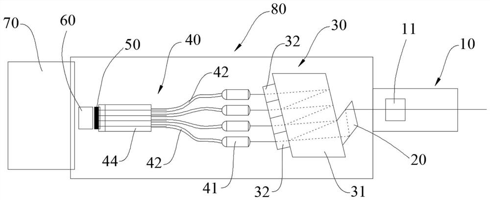
[0026] The present invention will be further described in detail below in conjunction with the accompanying drawings and specific embodiments. The descriptions of "first", "second" and so on in the present invention are only for the purpose of description, and should not be understood as indicating or implying their relative importance or implicitly indicating the quantity or order of the indicated technical features. Thus, the features defined as "first" and "second" may explicitly or implicitly include at least one of these features. In the description of the present invention, "plurality" means at least two, such as two, three, etc., unless otherwise specifically defined.

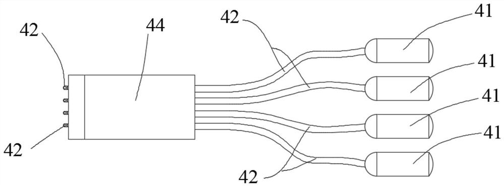
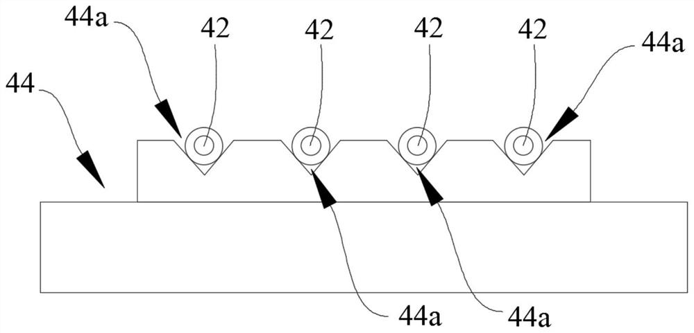
[0027] refer to Figure 1 to Figure 5 , the embodiment of the present application provides a multi-channel optical receiving module, including an incident collimator 11, a light splitting component 30, an optical path conversion component 40, and a photoelectric chip array 50 arranged in sequence, and t...


PUM

PropertyMeasurementUnit
angleaaaaaaaaaa

Abstract

The invention provides a multi-channel light receiving module, comprising an incident collimator, a light splitting component, an optical path conversion component and a photoelectric chip array arranged in sequence, the light splitting component includes an internal reflector and a plurality of optical filters, and the optical filters are respectively arranged At the output end of the internal reflector; the channel interval of the photoelectric chip in the photoelectric chip array is smaller than the channel interval of the adjacent filter; the optical path conversion component includes a plurality of outgoing collimators and optical fibers connected to each outgoing collimator, and splits the light. The multi-channel optical signals output by the component are respectively coupled into the corresponding optical fibers through a plurality of output collimators, and the multi-channel optical signals are output from the output ends of the multiple optical fibers and then coupled to the photoelectric chip array. The optical receiving module converts the optical path components from the large channel interval of the optical filter to the small channel interval of the photoelectric chip, which solves the problem that the channel interval between the optical filter and the photoelectric chip is difficult to match, reduces the cost of the photoelectric chip and reduces the cost of the photoelectric chip. The difficulty of assembling the filter.

Description

technical field [0001] The invention relates to the technical field of optical communication, in particular to a multi-channel optical receiving module. Background technique [0002] The optical transmitting module and the optical receiving module are the key components in the optical communication system. With the continuous increase of the capacity of the optical communication system, the rate of the optical transceiver module is also increasing. The transimpedance amplifier TIA, optoelectronic chip and light splitting component are the three main core parts of the light receiving module. In order to facilitate batch packaging, the three core components generally adopt the same channel spacing. Generally, the channel spacing between TIA and optoelectronic chip has dimensions of 750 μm, 500 μm and 250 μm. The smaller the channel spacing between the TIA and the optoelectronic chip, the smaller the area of ​​the optoelectronic chip, and the same size wafer can produce more...

Claims


Application Information

Patent Timeline
Patent Type & Authority Patents(China)
IPC IPC(8): H04B10/25H04B10/60G02B6/42
CPCH04B10/60G02B6/4206G02B6/29365G02B6/4215G02B6/421G02B6/4214G02B6/4243G02B6/368G02B6/29367
Inventor 陈土泉刘成刚史如玉
Owner GUANGXUN SCI & TECH WUHAN
Learn More