Flue gas treatment device

A technology for flue gas treatment and flue gas treatment chamber, which is applied in the separation of dispersed particles, chemical instruments and methods, separation methods, etc., can solve the problem that the treatment efficiency of photochemical methods is difficult to meet the emission amount in the production process, and improve the efficiency of flue gas treatment. , Improve the quality of flue gas treatment, easy to observe the effect

Inactive Publication Date: 2020-07-14
徐明好
View PDF1 Cites 0 Cited by
  • Summary
  • Abstract
  • Description
  • Claims
  • Application Information

AI Technical Summary

Problems solved by technology

However, due to the fact that the photochemical treatment efficiency of this technical solution is difficult to meet the needs of the production process emissions, there is also a need to improve the flue gas treatment efficiency, ensure the balance of the liquid catalyst in the rotating state, improve the operation quality of the equipment, and improve the quality of the flue gas after entering the flue gas treatment chamber. Well-distributed technical issues

Method used


Image

  • Flue gas treatment device
  • Flue gas treatment device
  • Flue gas treatment device

Examples


Embodiment 1

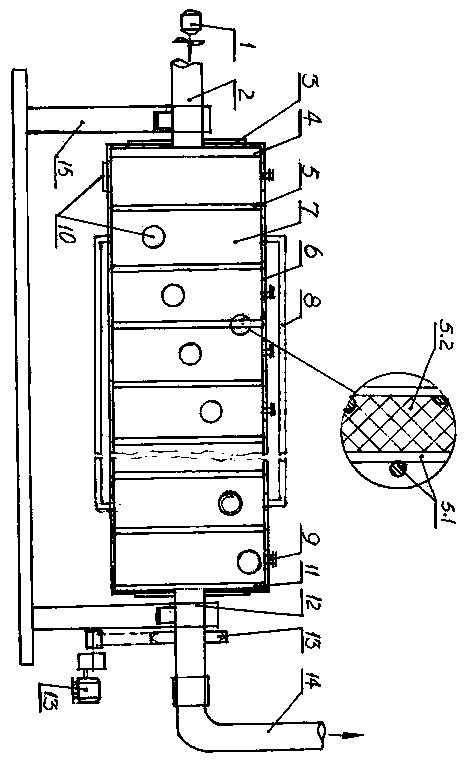
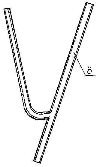
[0027] A flue gas treatment device of Example 1 of the present invention (see figure 1 ), including a frame 15, a flue gas input pipe 2, a flue gas treatment chamber 6 and a flue gas output pipe 14, wherein the flue gas input pipe 2 is arranged at the inlet end of the flue gas treatment chamber 6, and is connected with the flue gas treatment chamber 6 The inner cavities are connected, and an inlet end air distribution plate 4 is arranged at the end; 10 processing cavities 7 are evenly arranged in the inner cavities of the flue gas treatment chamber 6, and one between each two adjacent processing cavities 7 can carry The liquid catalyst can pass through the carrier interlayer 5 of the flue gas; the outer wall between the second processing chamber 7 of the flue gas processing chamber 6 and the penultimate processing chamber 7 at the end is symmetrically provided with two processing chambers respectively 7. The liquid catalyst balance conveying pipeline 8 that communicates with t...

Embodiment 2

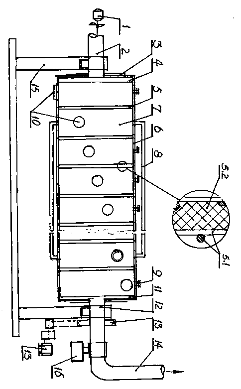
[0039] A kind of flue gas treatment device of embodiment 2 of the present invention (see figure 2 ), including a frame 15, a flue gas input pipe 2, a flue gas treatment chamber 6 and a flue gas output pipe 14. The inner cavities of the flue gas treatment chamber 6 are connected, and an inlet end air distribution plate 4 is arranged at the end; 15 treatment cavities 7 are evenly arranged in the inner cavities of the flue gas treatment chamber 6, and between every two adjacent treatment cavities 7 A carrier interlayer 5 that can carry liquid catalyst and pass through flue gas is provided; two The liquid catalyst balance conveying pipeline 8 communicated with the inner chamber of the processing chamber 7 respectively; the outlet end of the flue gas treatment chamber 6 is provided with an outlet end air distribution plate 11, and the outlet end air distribution plate 11 is connected with the inlet end air distribution plate 4 are arranged opposite to each other, and the outside ...

Embodiment 3

[0052] A kind of flue gas treatment device of embodiment 3 of the present invention (see figure 2 ), including a frame 15, a flue gas input pipe 2, a flue gas treatment chamber 6 and a flue gas output pipe 14. The inner cavities of the flue gas treatment chamber 6 are connected, and an inlet end air distribution plate 4 is provided at the end; 19 treatment cavities 7 are evenly arranged in the inner cavities of the flue gas treatment chamber 6, and between every two adjacent treatment cavities 7 A carrier interlayer 5 that can carry liquid catalyst and pass through flue gas is provided; two The liquid catalyst balance conveying pipeline 8 communicated with the inner chamber of the processing chamber 7 respectively; the outlet end of the flue gas treatment chamber 6 is provided with an outlet end air distribution plate 11, and the outlet end air distribution plate 11 is connected with the inlet end air distribution plate 4 are arranged opposite to each other, and the outside ...


PUM


Abstract

The invention discloses a flue gas treatment device, and relates to the technical field of flue gas treatment and environmental protection. According to the technical scheme, a flue gas input pipelineof the flue gas treatment device is arranged at the inlet end of a flue gas treatment chamber, and an inlet end air distribution plate is arranged at the end of the flue gas input pipeline; a plurality of treatment cavities are uniformly distributed in an inner cavity of the flue gas treatment chamber, and a carrier interlayer is arranged between every two adjacent treatment cavities; a conveyingpipeline is arranged between the second treatment cavity of the flue gas treatment chamber and the last but one treatment cavity at the tail end; the centers of the two ends of the flue gas treatmentchamber are each sleeved with a rolling bearing, and the rolling bearings are supported on the rack and connected with a power driving mechanism. Compared with the prior art, the device has the outstanding substantive characteristics and remarkable progress that the structure is more reasonable, secondary pollution is avoided, equipment operation is safe and reliable, and the flue gas treatment efficiency can be improved.

Description

technical field [0001] The invention relates to the technical field of flue gas treatment and environmental protection, in particular to the technical field of a flue gas treatment device. Background technique [0002] As we all know, the atmosphere is a mixture composed of a certain proportion of nitrogen, oxygen, carbon dioxide, water vapor and solid impurity particles. As far as dry air is concerned, calculated by volume, under standard conditions, nitrogen accounts for 78.08%, oxygen accounts for 20.94%, rare Gas accounts for 0.93%, carbon dioxide accounts for 0.03%, and the volume of other gases and impurities is about 0.02%. Various natural changes often cause changes in atmospheric composition, and when harmful gases and pollutants in the atmosphere reach a certain concentration, they will Bring great disaster to human beings and the environment. In addition to natural disasters such as volcanic eruptions, wildfires, earthquakes, and plagues, the main cause of air po...

Claims


Application Information

Patent Timeline
Patent Type & Authority Applications(China)
IPC IPC(8): B01D53/86
CPCB01D53/86
Inventor 徐明好
Owner 徐明好
Why Eureka
Try Eureka