Silicon rod squaring and polishing integrated machine

An all-in-one machine and silicon rod technology, which is applied to the parts of grinding machine tools, machine tools suitable for grinding the edge of workpieces, and machine tools designed for grinding the rotating surface of workpieces, etc., can solve the problem of increasing silicon rod grinding allowance and space Mutual interference, prolonging the processing time of silicon rods and other issues, to achieve the effect of improving transfer efficiency, improving work efficiency and saving space

Pending Publication Date: 2020-07-14
QINGDAO GAOCE TECH CO LTD
View PDF0 Cites 5 Cited by
  • Summary
  • Abstract
  • Description
  • Claims
  • Application Information

AI Technical Summary

Problems solved by technology

In the previous crystal silicon squaring, grinding and pouring all-in-one machine, the transfer of silicon rods between the squaring mechanism and the grinding and polishing mechanism used a manipulator. The manipulator has the characteristics of convenient transfer, but due to the limitation of equipment space and other factors, multiple manipulators often Therefore, generally only one manipulator is set between the squaring mechanism and the grinding and polishing mechanism, so that a manipulator can only hold a silicon rod at the squaring mechanism or at the grinding mechanism. Grinding, when one of the grinding mechanism or the squaring mechanism is working, the other is in an idle state, which restricts the utilization rate of the equipment and affects the processing efficiency of the silicon rod. After the prescription is completed, when the silicon rods are transported to the grinding and polishing mechanism for grinding and polishing, the silicon rods need to be clamped twice. The secondary clamping will easily increase the grinding allowance of the silicon rods and prolong the processing time of the silicon rods. Therefore, how to reduce the number of clamping times in the processing of silicon rods and improve the processing efficiency of silicon rods is a problem we need to solve

Method used


Image

  • Silicon rod squaring and polishing integrated machine
  • Silicon rod squaring and polishing integrated machine
  • Silicon rod squaring and polishing integrated machine

Examples


Embodiment 1

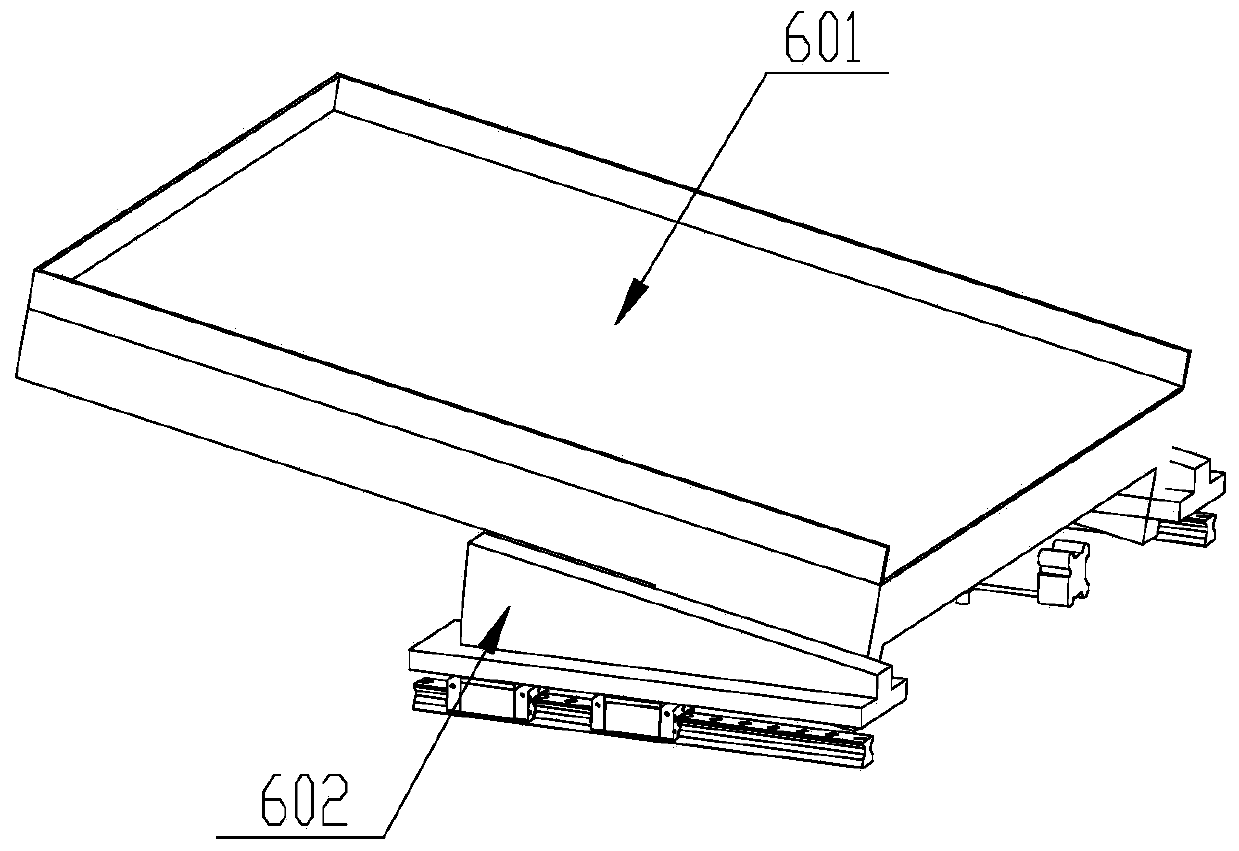
[0047] refer to figure 1 , image 3 The edge skin mechanism 6 includes a material receiving box 601 and a material receiving box fixing seat 602. The material receiving box 601 is obliquely arranged on the upper part of the material receiving box fixing seat 602, and is slidably connected with the material receiving box fixing seat 602. The cartridge holder 602 is disposed on the base 1 and is slidably connected with the base 1 . Specifically, two feeding slide rails are arranged on the base 1 along the conveying direction of the crystal silicon, and a first air cylinder is arranged horizontally between the feeding slide rails, and the first air cylinder is arranged parallel to the feeding slide rails. The first air cylinder is slidingly matched with the material receiving slide rail, that is, the first air cylinder drives the material receiving box 601 to generate displacement along the crystal silicon conveying direction. Simultaneously, a slideway for the material receivi...

Embodiment 2

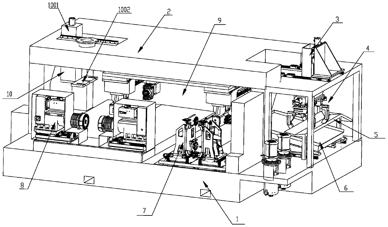
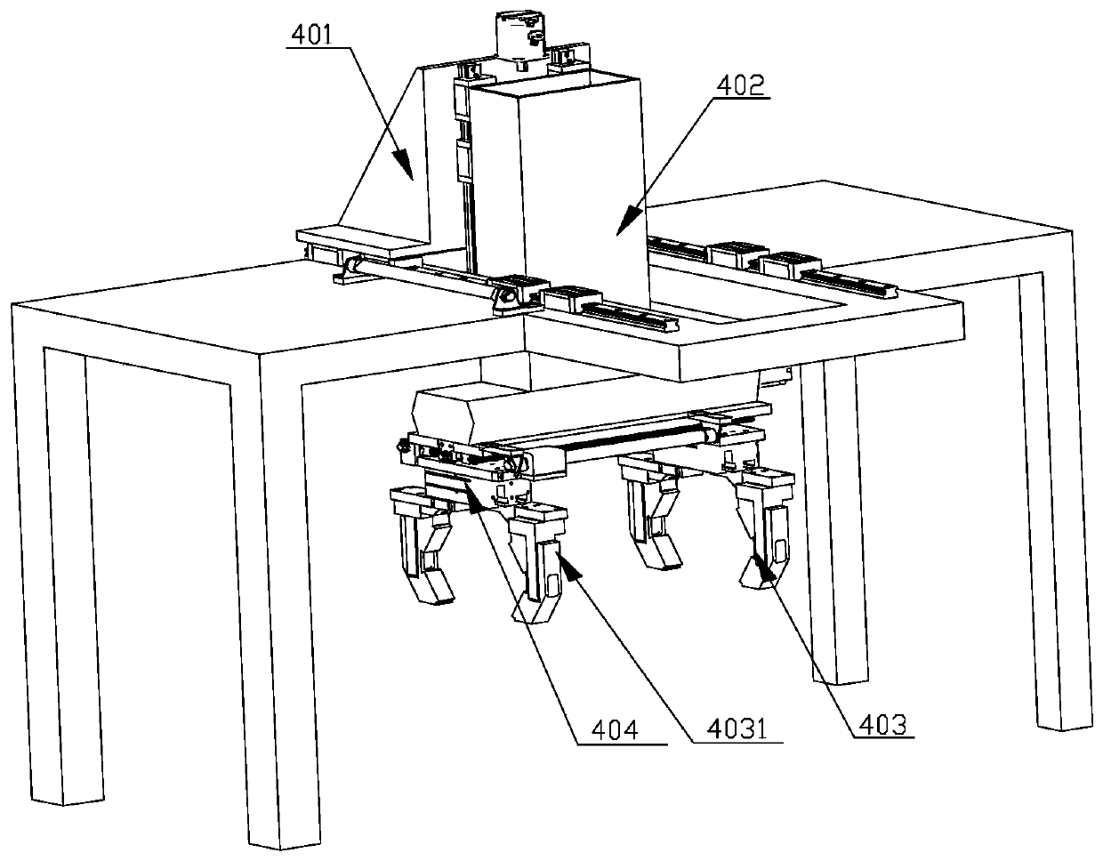
[0050] refer to figure 1 , figure 2 , the feeding mechanism 3 includes a manipulator assembly 4 and a feeding table 5, the feeding table 5 straddles the top of the edge leather mechanism 6, and is fixedly connected to the base 1 through a feeding table bracket. The manipulator assembly 4 is arranged above the loading platform 5 and is slidably connected with the support frame 2 .

[0051] Specifically, the manipulator assembly 4 includes a manipulator fixing base 401, a manipulator supporting base 402 and a jaw assembly 403, the manipulator fixing base 401 is slidably connected with the support frame 2 in the horizontal direction, the manipulator supporting base 402 and the manipulator fixing base 401 Slidingly connected in the vertical direction, the jaw assembly 403 is arranged below the manipulator support base 402 and is slidably connected with the manipulator support base 402 in the horizontal direction.

[0052] In this embodiment, the conveying direction of the silic...

Embodiment 3

[0056] refer to figure 1 , Figure 4 , the square finding mechanism 7 includes a cutting head, and the cutting head includes a cutting channel surrounded by cutting lines through which the crystalline silicon passes and cuts.

[0057] Specifically, the cutting head includes a cutting base 701, a left cutting assembly 702 and a right cutting assembly 703, and the left cutting assembly 702 and the right cutting assembly 703 are arranged on the cutting base 701 at intervals with the central axis of the cutting base 701 as a symmetrical axis , and a cutting channel for the passage of crystal silicon is formed between the two, and the cutting base 701 is slidably connected with the base 1 through the first lead screw 704 . Specifically, the first lead screw 704 is arranged on the base 1 along the horizontal direction, and is located below the cutting base 701. Fixed connection to realize the sliding connection between the cutting base 701 and the base 1.

[0058] The left cuttin...


PUM


Abstract

The invention relates to a silicon rod squaring and polishing integrated machine and belongs to the field of crystalline silicon processing equipment. The silicon rod squaring and polishing integratedmachine comprises a base and a supporting frame which is positioned above the base and is fixedly connected to the base; a feeding mechanism, a flaw-piece receiving mechanism, a squaring mechanism and a polishing mechanism are arranged on the base sequentially in a conveying direction of a silicon rod; a rotary conveying mechanism is arranged between the squaring mechanism and the polishing mechanism; the rotary conveying mechanism is fixedly connected to a supporting frame and is used for transferring the silicon rod between the squaring mechanism and the polishing mechanism; a discharging mechanism connected to the supporting frame is arranged at the position of the polishing mechanism and is used for transferring the processed silicon rod out of the base; and the rotary conveying mechanism can transfer two silicon rods simultaneously, and the squaring mechanism and the polishing mechanism are not in idle, so that the utilization ratio of the whole machine and the processing efficiency of the silicon rod are greatly enhanced, and high automation degree and wide market prospect are achieved.

Description

technical field [0001] The invention belongs to the technical field of crystal silicon processing equipment, and in particular relates to an all-in-one machine for square cutting and grinding of silicon rods. Background technique [0002] Photovoltaic power generation is one of the most important clean energy sources with great development potential. The key factors restricting the development of photovoltaic industry are low photoelectric conversion efficiency on the one hand and high cost on the other hand. Photovoltaic silicon wafers are the basic material for the production of solar cells and modules. The actual production of a single silicon rod involves processes such as preparation, edge trimming, surface grinding, polishing, chamfering, slicing, battery slices, and components. In the previous crystal silicon squaring, grinding and pouring all-in-one machine, the transfer of silicon rods between the squaring mechanism and the grinding and polishing mechanism used a ...

Claims


Application Information

Patent Timeline
Patent Type & Authority Applications(China)
IPC IPC(8): B24B27/00B24B5/50B24B9/06B24B41/06B24B41/00B28D5/04B28D7/04B28D7/00
CPCB24B5/50B24B9/065B24B27/0076B24B27/0092B24B41/005B24B41/06B28D5/045B28D7/00B28D7/04
Inventor 郭世锋徐公志刘克村尹美玲
Owner QINGDAO GAOCE TECH CO LTD
Why Eureka
Try Eureka