Eureka AIR delivers breakthrough ideas for toughest innovation challenges, trusted by R&D personnel around the world.

Anti-electrochemical corrosion radiator heat pipe embedding structure

A technology of chemical corrosion and embedded structure, applied in the direction of heat exchanger shell, indirect heat exchanger, heat exchange equipment, etc., can solve the problems of inappropriate, high cost of overall surface plating, process environment pollution, etc., to avoid the electrolyte The effect of forming and solving the problem of electrochemical corrosion

Pending Publication Date: 2020-07-24
江苏海鋆自动化技术有限公司
View PDF0 Cites 1 Cited by
  • Summary
  • Abstract
  • Description
  • Claims
  • Application Information

AI Technical Summary

Problems solved by technology

[0003] 1. The whole surface of the radiator is electroplated and then buried and welded by tin to realize the covering of copper tubes and isolate the air to solve the problem of corrosion potential, but the cost of overall surface electroplating is high, and the process pollutes the environment seriously;
[0004] 2. The radiator aluminum substrate is used to penetrate the deep hole, and the heat pipe is inserted into the deep hole to fix and close the gap with glue, but the processing cost is high, and the heat dissipation efficiency of the gap between the heat pipe and the aluminum is low. Currently, only Furukawa, Japan adopts this process;
[0005] 3. Epoxy resin is used to bond the heat pipe and the aluminum substrate of the radiator, but the copper and aluminum are exposed in the air, which is not suitable for outdoor natural conditions

Method used


Image

  • Anti-electrochemical corrosion radiator heat pipe embedding structure
  • Anti-electrochemical corrosion radiator heat pipe embedding structure
  • Anti-electrochemical corrosion radiator heat pipe embedding structure

Examples


Embodiment Construction

[0018] The following will clearly and completely describe the technical solutions in the embodiments of the present invention with reference to the accompanying drawings in the embodiments of the present invention. Obviously, the described embodiments are only some, not all, embodiments of the present invention. Based on the embodiments of the present invention, all other embodiments obtained by persons of ordinary skill in the art without making creative efforts belong to the protection scope of the present invention.

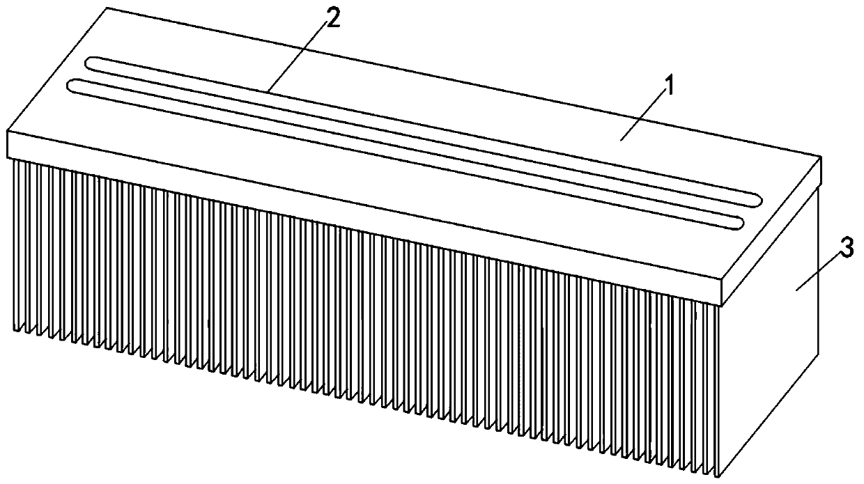
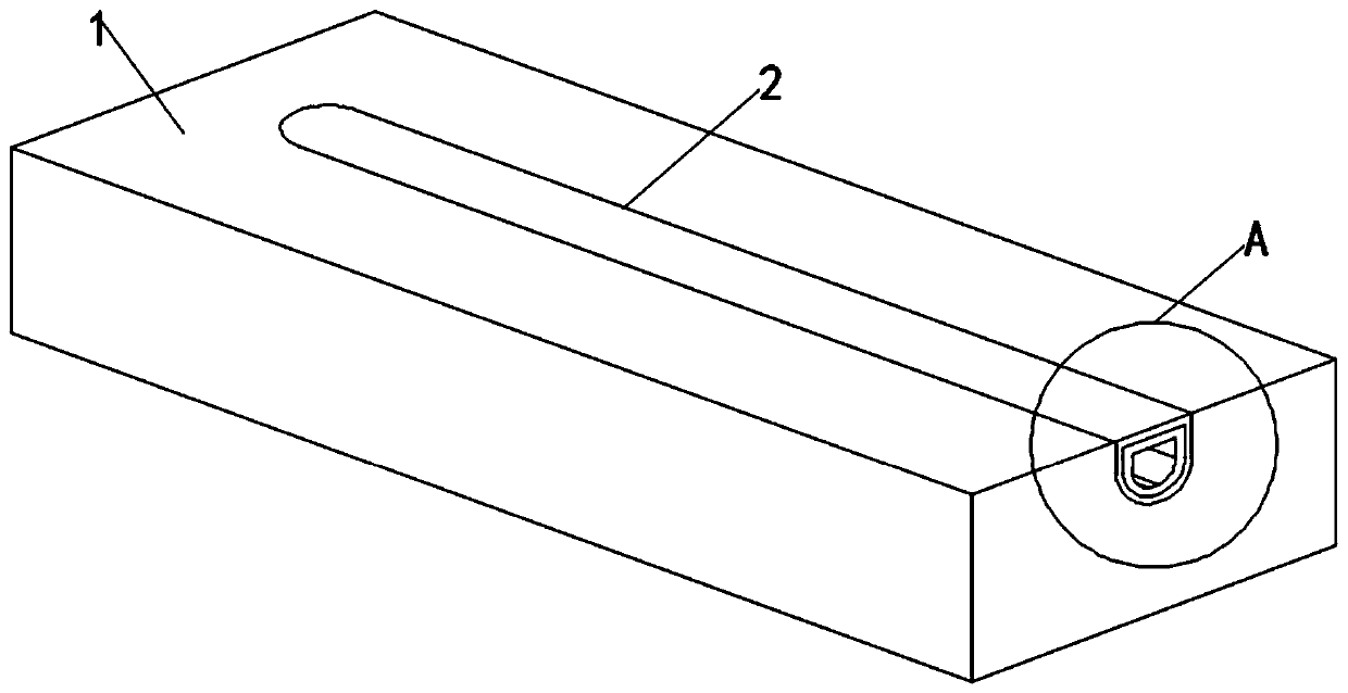
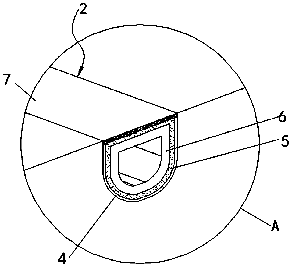
[0019] see Figure 1-3 , in an embodiment of the present invention, an anti-electrochemical corrosion radiator heat pipe embedding structure includes a radiator aluminum substrate 1, a groove 2 is opened on the upper surface of the radiator aluminum substrate 1, and a heat dissipation device is fixedly connected to the lower surface of the radiator aluminum substrate 1. The fin plate 3 and the inner wall of the groove 2 are provided with a solder flux coating ...


PUM

PropertyMeasurementUnit
Thicknessaaaaaaaaaa
Thicknessaaaaaaaaaa

Abstract

The invention discloses an anti-electrochemical corrosion radiator heat pipe embedding structure, and relates to the technical field of heat pipe radiators. The anti-electrochemical corrosion radiatorheat pipe embedding structure comprises a radiator aluminum substrate, a groove is formed in the upper surface of the radiator aluminum substrate, a radiating fin plate is fixedly connected to the lower surface of the radiator aluminum substrate, a welding aid coating is arranged on the inner wall of the groove, a heat pipe is arranged in the groove in an embedded mode, a heat pipe sintered wickis arranged in the heat pipe in an embedded mode, a soldering layer is arranged on the upper surface of the heat pipe, and the peripheral side walls of the soldering layer are in close fit with the welding aid coating correspondingly. According to the anti-electrochemical corrosion radiator heat pipe embedding structure, the soldering layer and the welding aid coating are arranged, the heat pipe is welded and buried by soldering by means of partial surface treatment, thus the seamless soldering layer is formed on the upper surface of the heat pipe, meanwhile the soldering layer and the weldingaid coating are welded seamlessly, so that the outer surface of the pipe wall of the heat pipe is protected by the soldering layer to isolate air, so as to avoid the formation of an electrolyte, andthe purpose of solving the problem of electrochemical corrosion is achieved.

Description

technical field [0001] The invention relates to the technical field of heat pipe radiators, in particular to a heat pipe embedding structure for an anti-electrochemical corrosion radiator. Background technique [0002] Heat pipe radiator is a new product produced by using heat pipe technology to make significant improvements to many old radiators or heat exchange products and systems. There are two types of heat pipe radiators: natural cooling and forced air cooling. The thermal resistance of air-cooled heat pipe radiators can be made smaller, and they are often used in high-power power supplies. The existing heat pipe radiators are directly glued or The form of welding directly fills the heat pipe in the pre-processed heat pipe groove. The copper and aluminum are exposed in the air, but the copper and aluminum are connected together by a simple mechanical method. Electrochemical corrosion is prone to occur in the medium, which will lead to the failure of the heat pipe radi...

Claims


Application Information

Patent Timeline
IPC IPC(8): F28D15/02F28F19/00F28F21/08F28F9/18
CPCF28D15/02F28F9/18F28F19/00F28F21/084
Inventor 潘建锋
Owner 江苏海鋆自动化技术有限公司
Why Eureka
Eureka Blog
Learn More