
Dielectric resonance antenna

A dielectric resonant antenna, dielectric resonator technology, applied in resonant antennas, antennas, electrical short antennas and other directions, can solve the problems of excessive volume of dielectric resonant antennas, the radiation effect needs to be improved, etc., and achieves simple structure, low loss, and easy processing. Effect

Inactive Publication Date: 2020-07-24
ZHONGTIAN BROADBAND TECH +1
View PDF3 Cites 5 Cited by
  • Summary
  • Abstract
  • Description
  • Claims
  • Application Information

AI Technical Summary

Problems solved by technology

[0003] The main purpose of the present invention is to provide a dielectric resonant antenna, which aims to solve the problem that the dielectric resonant antenna in the prior art is too large and the radiation effect needs to be improved

Method used


Image

  • Dielectric resonance antenna
  • Dielectric resonance antenna
  • Dielectric resonance antenna

Examples


Embodiment Construction

[0026] The following will clearly and completely describe the technical solutions in the embodiments of the present invention with reference to the accompanying drawings in the embodiments of the present invention. Obviously, the described embodiments are only part of the embodiments of the present invention, not all of them. Based on the embodiments of the present invention, all other embodiments obtained by persons of ordinary skill in the art without making creative efforts belong to the protection scope of the present invention.

[0027] It should be noted that all directional indications (such as up, down, left, right, front, back...) in the embodiments of the present invention are only used to explain the relationship between the components in a certain posture (as shown in the accompanying drawings). Relative positional relationship, movement conditions, etc., if the specific posture changes, the directional indication will also change accordingly.

[0028] In addition,...


PUM


Abstract

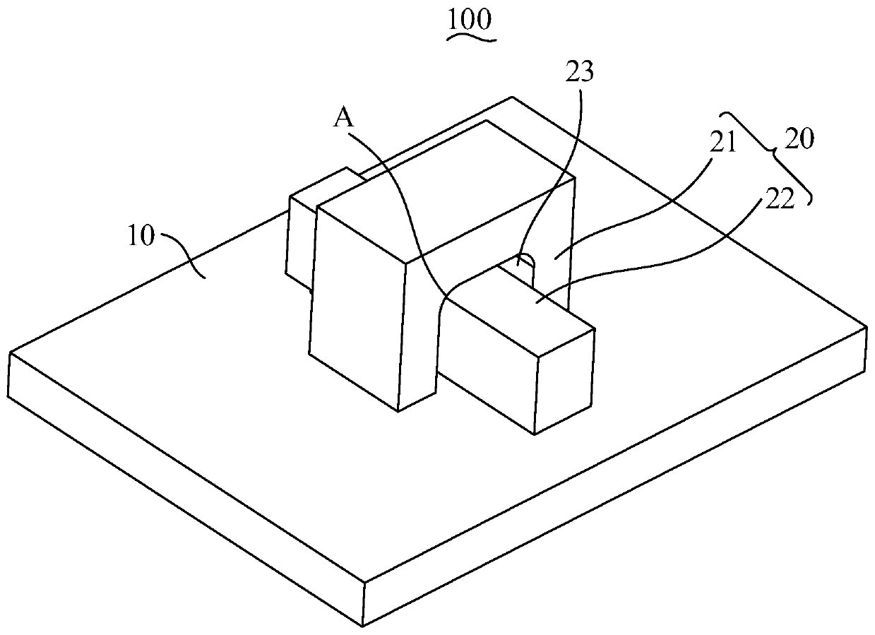
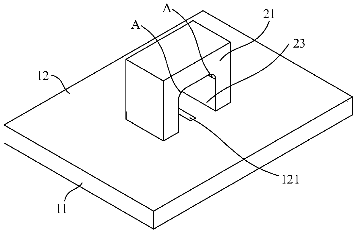
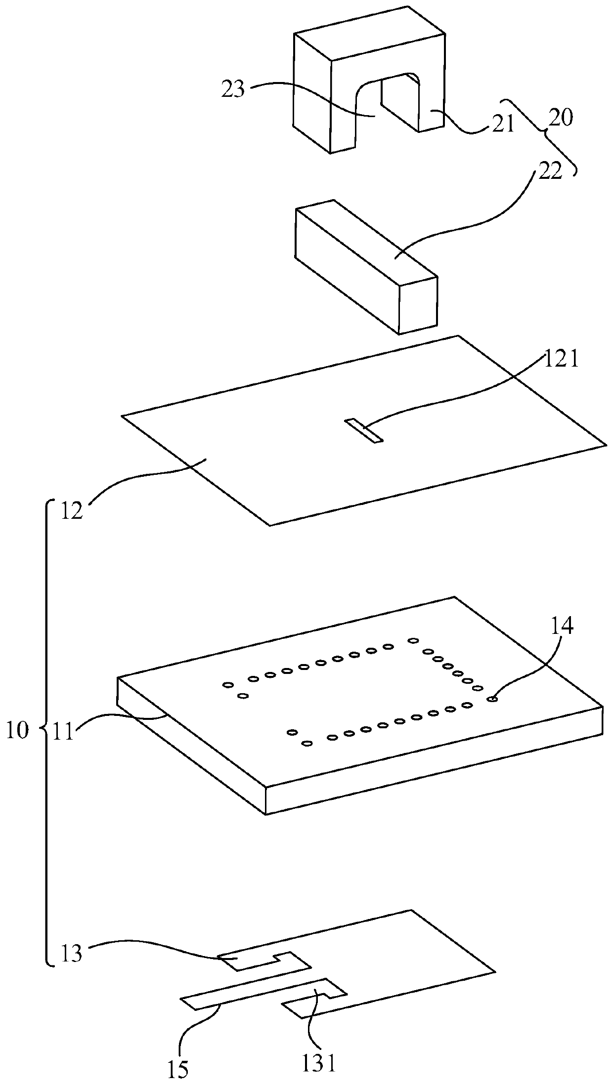
The invention discloses a dielectric resonant antenna. The dielectric resonant antenna comprises a filtering feed module and a dielectric resonator, wherein the dielectric resonator is arranged on thefiltering feed module in a stacked mode, the filtering feed module is used for feeding the dielectric resonator, the dielectric resonator includes a first dielectric block and a second dielectric block, and the second dielectric block is arranged in the first dielectric block in a penetrating mode. The dielectric resonant antenna disclosed by the invention can realize directional radiation in a 24.75-27.5 GHz frequency band, has advantages of s small loss, high radiation efficiency, s low profile, s small outline, s simple structure, easiness in processing and the like, and is very suitable for a 5G indoor communication system.

Description

technical field [0001] The invention relates to the technical field of communication, in particular to a dielectric resonant antenna. Background technique [0002] Modern communication has put forward higher and higher requirements for the miniaturization and low loss of the antenna. The traditional microstrip antenna has high metal loss in the high frequency band, and the antenna size is large in the low frequency band. Its development and application prospects are restricted. Certain restrictions. The dielectric resonant antenna is a kind of resonant antenna that has emerged in the past ten years. The radiating unit is composed of dielectric materials. Since the dielectric resonator is a pure dielectric structure and has no metal loss, the loss of the dielectric resonant antenna can be small and has high radiation. efficiency. At the same time, dielectric resonant antennas also have the advantages of easy miniaturization, broadband, multi-band, simple processing, and eas...

Claims


Application Information

Patent Timeline
IPC IPC(8): H01Q1/36H01Q1/50H01Q9/04
CPCH01Q9/0485H01Q1/36H01Q1/50
Inventor 葛盈飞王建朋
Owner ZHONGTIAN BROADBAND TECH
Learn More